Removal [12/2015 - 08/2016]: Procedure
WARNING: This page is about a different car, the 2016 Toyota Sienna. However, it is still accessible from the selected car via links, so may be relevant.
- INSTALL ENGINE ON ENGINE STAND
- Install the engine onto an engine stand with the bolts.
- REMOVE ENGINE HANGER
- Remove the 4 bolts and 2 engine hangers.
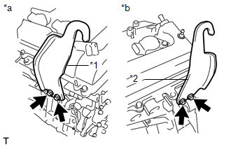 Courtesy of © TOYOTA, LICENSE AGREEMENT TMS1002 Courtesy of © TOYOTA, LICENSE AGREEMENT TMS1002
|
TEXT IN ILLUSTRATION
| *1 |
No. 1 engine hanger |
| *2 |
No. 2 engine hanger |
| *a |
Bank 1 |
| *b |
Bank 2 |
- REMOVE INTAKE AIR SURGE TANK ASSEMBLY
Refer to PROCEDURE - Step 5
- REMOVE NO. 1 SURGE TANK STAY
- Remove the bolt and No. 1 surge tank stay.
 Courtesy of © TOYOTA, LICENSE AGREEMENT TMS1002 Courtesy of © TOYOTA, LICENSE AGREEMENT TMS1002
|
- REMOVE THROTTLE BODY BRACKET
- Remove the bolt and throttle body bracket.
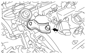 Courtesy of © TOYOTA, LICENSE AGREEMENT TMS1002 Courtesy of © TOYOTA, LICENSE AGREEMENT TMS1002
|
- REMOVE IGNITION COIL ASSEMBLY
Refer to PROCEDURE - Step 3
- REMOVE NO. 2 ENGINE MOUNTING STAY RH
- Remove the bolt and No. 2 engine mounting stay RH.
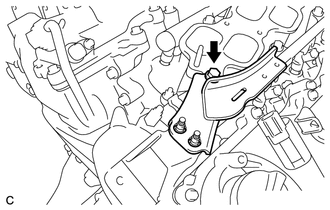 Courtesy of © TOYOTA, LICENSE AGREEMENT TMS1002 Courtesy of © TOYOTA, LICENSE AGREEMENT TMS1002
|
- REMOVE FUEL HOSE PROTECTOR
- Remove the 2 bolts and nut, and then remove the fuel hose protector.
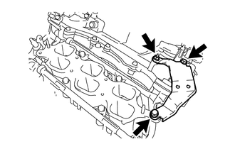 Courtesy of © TOYOTA, LICENSE AGREEMENT TMS1002 Courtesy of © TOYOTA, LICENSE AGREEMENT TMS1002
|
- REMOVE INTAKE MANIFOLD
- Uniformly loosen and remove the 6 bolts and 4 nuts.
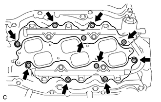 Courtesy of © TOYOTA, LICENSE AGREEMENT TMS1002 Courtesy of © TOYOTA, LICENSE AGREEMENT TMS1002
|
- Remove the intake manifold and 2 gaskets.
- REMOVE EXHAUST MANIFOLD SUB-ASSEMBLY RH
- Uniformly loosen and remove the 6 nuts.
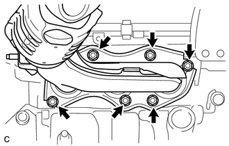 Courtesy of © TOYOTA, LICENSE AGREEMENT TMS1002 Courtesy of © TOYOTA, LICENSE AGREEMENT TMS1002
|
- Remove the exhaust manifold sub-assembly RH and gasket.
- REMOVE NO. 2 ENGINE OIL LEVEL DIPSTICK GUIDE
- Remove the oil level dipstick.
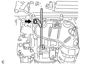 Courtesy of © TOYOTA, LICENSE AGREEMENT TMS1002 Courtesy of © TOYOTA, LICENSE AGREEMENT TMS1002
|
- Remove the bolt and No. 2 engine oil level dipstick guide.
- Remove the O-ring from the No. 2 engine oil level dipstick guide.
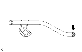 Courtesy of © TOYOTA, LICENSE AGREEMENT TMS1002 Courtesy of © TOYOTA, LICENSE AGREEMENT TMS1002
|
- REMOVE NO. 2 MANIFOLD STAY
Refer to PROCEDURE - Step 14
- REMOVE NO. 2 EXHAUST MANIFOLD HEAT INSULATOR
Refer to PROCEDURE - Step 15
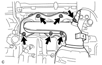
- REMOVE EXHAUST MANIFOLD SUB-ASSEMBLY LH
- Uniformly loosen and remove the 6 nuts.
 Courtesy of © TOYOTA, LICENSE AGREEMENT TMS1002 Courtesy of © TOYOTA, LICENSE AGREEMENT TMS1002
|
- Remove the exhaust manifold assembly LH and gasket.
- REMOVE V-RIBBED BELT TENSIONER ASSEMBLY
- Remove the 5 bolts and V-ribbed belt tensioner assembly.
 Courtesy of © TOYOTA, LICENSE AGREEMENT TMS1002 Courtesy of © TOYOTA, LICENSE AGREEMENT TMS1002
|
- REMOVE NO. 2 TIMING GEAR COVER
- Remove the 2 bolts and No. 2 timing gear cover.
 Courtesy of © TOYOTA, LICENSE AGREEMENT TMS1002 Courtesy of © TOYOTA, LICENSE AGREEMENT TMS1002
|
- REMOVE WATER PUMP PULLEY
Refer to PROCEDURE - Step 10
- REMOVE NO. 2 IDLER PULLEY SUB-ASSEMBLY
- Remove the bolt, No. 2 idler pulley cover plate, No. 2 idler pulley sub-assembly and idler pulley cover plate.
 Courtesy of © TOYOTA, LICENSE AGREEMENT TMS1002 Courtesy of © TOYOTA, LICENSE AGREEMENT TMS1002
|
- REMOVE NO. 1 VACUUM SWITCHING VALVE ASSEMBLY
- Remove the bolt and No. 1 vacuum switching valve.
 Courtesy of © TOYOTA, LICENSE AGREEMENT TMS1002 Courtesy of © TOYOTA, LICENSE AGREEMENT TMS1002
|
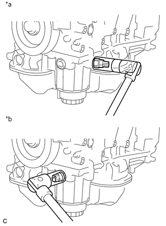
- REMOVE ENGINE OIL PRESSURE SWITCH ASSEMBLY
- Using a deep socket wrench, remove the engine oil pressure switch assembly.
 Courtesy of © TOYOTA, LICENSE AGREEMENT TMS1002 Courtesy of © TOYOTA, LICENSE AGREEMENT TMS1002
|
TEXT IN ILLUSTRATION
| *a |
w/o Oil Cooler |
| *b |
w/ Oil Cooler |
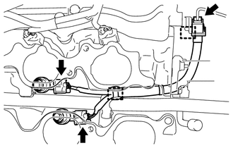
- REMOVE KNOCK SENSOR WIRE
- Disconnect the 2 knock sensor connectors and knock sensor wire connector.
 Courtesy of © TOYOTA, LICENSE AGREEMENT TMS1002 Courtesy of © TOYOTA, LICENSE AGREEMENT TMS1002
|
- Disconnect the 2 clamps and remove the knock sensor wire from the engine assembly.
- REMOVE KNOCK SENSOR
Refer to PROCEDURE - Step 2
- REMOVE ENGINE COOLANT TEMPERATURE SENSOR
Refer to PROCEDURE - Step 8