- DISCHARGE FUEL SYSTEM PRESSURE
(Refer to ON-VEHICLE INSPECTION [08/2015 - ]
)
- DRAIN ENGINE OIL
See step 1[08/2015 - 08/2019]
See step 1[08/2019 - 08/2021]
See step 1[08/2021 - ]
- REMOVE RADIATOR ASSEMBLY
(Refer to REMOVAL [08/2015 - ]
)
- REMOVE AIR CLEANER ASSEMBLY
Refer to PROCEDURE - Step 4
- REMOVE AIR CLEANER HOSE ASSEMBLY
Refer to PROCEDURE - Step 5
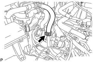
- DISCONNECT INLET HEATER WATER HOSE C
- Slide the clamp and disconnect the inlet heater water hose C from the water by-pass pipe sub-assembly.
 Courtesy of © TOYOTA, LICENSE AGREEMENT TMS1002 Courtesy of © TOYOTA, LICENSE AGREEMENT TMS1002
|
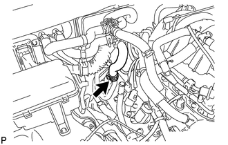
- DISCONNECT OUTLET HEATER WATER HOSE C
- Slide the clamp and disconnect the outlet heater water hose C from the No. 1 water by-pass pipe.
 Courtesy of © TOYOTA, LICENSE AGREEMENT TMS1002 Courtesy of © TOYOTA, LICENSE AGREEMENT TMS1002
|
- SEPARATE ENGINE WIRE
- SEPARATE NO. 2 ENGINE WIRE
- REMOVE INTAKE MANIFOLD
(Refer to REMOVAL [08/2015 - ]
).
- DISCONNECT NO. 3 AIR INJECTION SYSTEM HOSE
Refer to PROCEDURE - Step 4
- DISCONNECT NO. 2 AIR INJECTION SYSTEM HOSE
Refer to PROCEDURE - Step 5
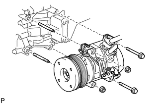
- SEPARATE COOLER COMPRESSOR ASSEMBLY
- Remove the 2 bolts, 2 nuts and 2 stud bolts, and disconnect the cooler compressor assembly.
 Courtesy of © TOYOTA, LICENSE AGREEMENT TMS1002 Courtesy of © TOYOTA, LICENSE AGREEMENT TMS1002
|
HINT:
It is not necessary to completely remove the cooler compressor assembly. With the hoses connected to the cooler compressor assembly, hang the cooler compressor assembly on the vehicle body with a rope.
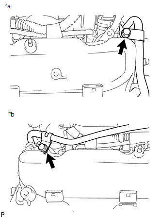
- SEPARATE NO. 2 FUEL TUBE SUB-ASSEMBLY
- Remove the 2 bolts and separate the No. 2 fuel tube sub-assembly.
 Courtesy of © TOYOTA, LICENSE AGREEMENT TMS1002 Courtesy of © TOYOTA, LICENSE AGREEMENT TMS1002
|
TEXT IN ILLUSTRATION
- REMOVE OIL FILTER ELEMENT
Refer to:
REPLACEMENT [08/2015 - 08/2019] , or refer to
REPLACEMENT [08/2019 - 08/2021] , or refer to
REPLACEMENT [08/2021 - ]
- REMOVE OIL PRESSURE SENDER GAUGE ASSEMBLY (w/o Trailer Towing System)
See step 2
- REMOVE ENGINE OIL COOLER (w/ Trailer Towing System)
(Refer to REMOVAL [08/2015 - ] )
- REMOVE OIL FILTER BRACKET (w/o Trailer Towing System)
See step 9
- REMOVE ENGINE OIL LEVEL DIPSTICK GUIDE
Refer to:
PROCEDURE - Step 5 [08/2015 - 08/2019]
PROCEDURE - Step 5 [08/2019 - ]
- REMOVE GENERATOR ASSEMBLY
(Refer to REMOVAL [08/2015 - ]
)
- REMOVE NO. 1 WATER BY-PASS HOSE
- Slide the 2 clamps and remove the No. 1 water by-pass hose from the inlet water housing and front water by-pass joint.
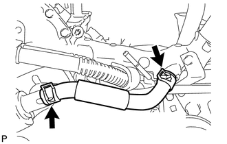 Courtesy of © TOYOTA, LICENSE AGREEMENT TMS1002 Courtesy of © TOYOTA, LICENSE AGREEMENT TMS1002
|
- SEPARATE AIR PIPE SUB-ASSEMBLY
Refer to PROCEDURE - Step 6
- REMOVE WATER BY-PASS PIPE SUB-ASSEMBLY
- Slide the 2 clamps and disconnect the No. 2 water by-pass hose and No. 3 water by-pass hose from the water by-pass pipe sub-assembly.
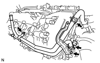 Courtesy of © TOYOTA, LICENSE AGREEMENT TMS1002 Courtesy of © TOYOTA, LICENSE AGREEMENT TMS1002
|
- Remove the 2 bolts and water by-pass pipe sub-assembly.
- SEPARATE NO. 1 WATER BY-PASS PIPE
- Remove the 2 bolts and separate the No. 1 water by-pass pipe.
- DISCONNECT NO. 9 WATER BY-PASS HOSE
- Slide the clamp and disconnect the No. 9 water by-pass hose from the front water by-pass joint.
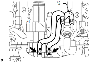 Courtesy of © TOYOTA, LICENSE AGREEMENT TMS1002 Courtesy of © TOYOTA, LICENSE AGREEMENT TMS1002
|
TEXT IN ILLUSTRATION
| *1 |
No. 9 Water By-pass Hose |
| *2 |
No. 10 Water By-pass Hose |
- DISCONNECT NO. 10 WATER BY-PASS HOSE
- Slide the clamp and disconnect the No. 10 water by-pass hose from the front water by-pass joint.
- REMOVE FRONT WATER BY-PASS JOINT
- Slide the clamp and disconnect the No. 2 water by-pass hose from the front water by-pass joint.
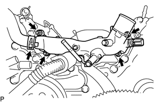 Courtesy of © TOYOTA, LICENSE AGREEMENT TMS1002 Courtesy of © TOYOTA, LICENSE AGREEMENT TMS1002
|
- Remove the 4 nuts, front water by-pass joint and 2 gaskets.
- REMOVE NO. 2 CYLINDER HEAD COVER
Refer to PROCEDURE - Step 9
- REMOVE NO. 1 ENGINE COVER
Refer to PROCEDURE - Step 11
- REMOVE AIR PIPE SUB-ASSEMBLY
- Remove the bolt, disconnect the 2 hoses, and remove the air pipe sub-assembly.
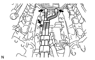 Courtesy of © TOYOTA, LICENSE AGREEMENT TMS1002 Courtesy of © TOYOTA, LICENSE AGREEMENT TMS1002
|
- REMOVE INLET WATER HOUSING
Refer to PROCEDURE - Step 15
- REMOVE WATER PUMP PULLEY
Refer to PROCEDURE - Step 16
- REMOVE NO. 1 IDLER PULLEY SUB-ASSEMBLY
- Remove the bolt and No. 1 idler pulley sub-assembly.
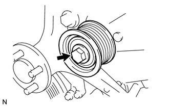 Courtesy of © TOYOTA, LICENSE AGREEMENT TMS1002 Courtesy of © TOYOTA, LICENSE AGREEMENT TMS1002
|
- REMOVE FLUID COUPLING BRACKET
- Remove the 4 bolts and fluid coupling bracket.
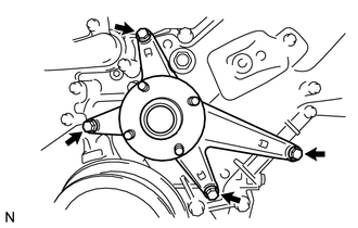 Courtesy of © TOYOTA, LICENSE AGREEMENT TMS1002 Courtesy of © TOYOTA, LICENSE AGREEMENT TMS1002
|
- REMOVE V-RIBBED BELT TENSIONER ASSEMBLY
- Remove the standard bolt, 6 mm hexagon wrench bolt and V-ribbed belt tensioner assembly.
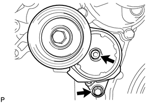 Courtesy of © TOYOTA, LICENSE AGREEMENT TMS1002 Courtesy of © TOYOTA, LICENSE AGREEMENT TMS1002
|
- REMOVE IGNITION COIL ASSEMBLY
Refer to PROCEDURE - Step 3
- REMOVE CYLINDER HEAD COVER SUB-ASSEMBLY LH
- Remove the 14 bolts, seal washer, cylinder head cover sub-assembly LH and gasket.
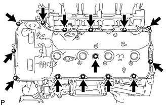 Courtesy of © TOYOTA, LICENSE AGREEMENT TMS1002 Courtesy of © TOYOTA, LICENSE AGREEMENT TMS1002
|
HINT:
Make sure that the removed parts are returned to the same places they were removed from.
- Remove the 5 O-rings from the No. 2 camshaft bearing cap and No. 3 camshaft bearing cap.
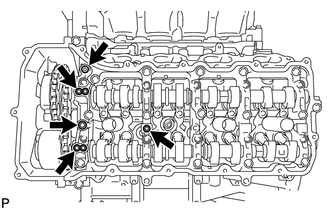 Courtesy of © TOYOTA, LICENSE AGREEMENT TMS1002 Courtesy of © TOYOTA, LICENSE AGREEMENT TMS1002
|
- REMOVE CYLINDER HEAD COVER SUB-ASSEMBLY
- Remove the 14 bolts, seal washer, cylinder head cover sub-assembly and gasket.
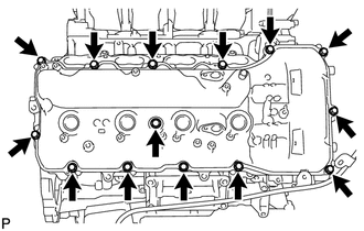 Courtesy of © TOYOTA, LICENSE AGREEMENT TMS1002 Courtesy of © TOYOTA, LICENSE AGREEMENT TMS1002
|
HINT:
Make sure that the removed parts are returned to the same places they were removed from.
- Remove the 5 O-rings from the No. 1 camshaft bearing cap and No. 3 camshaft bearing cap.
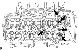 Courtesy of © TOYOTA, LICENSE AGREEMENT TMS1002 Courtesy of © TOYOTA, LICENSE AGREEMENT TMS1002
|
- REMOVE CRANKSHAFT PULLEY
Refer to PROCEDURE - Step 3
- DISCONNECT WIRE HARNESS CLAMP BRACKET
- Remove the bolt and disconnect the wire harness clamp bracket.
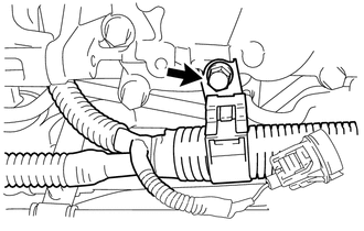 Courtesy of © TOYOTA, LICENSE AGREEMENT TMS1002 Courtesy of © TOYOTA, LICENSE AGREEMENT TMS1002
|
- REMOVE TIMING CHAIN OR BELT COVER SUB-ASSEMBLY
- Remove the 28 bolts and nut shown in the illustration.
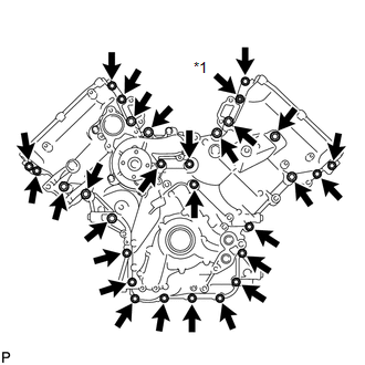 Courtesy of © TOYOTA, LICENSE AGREEMENT TMS1002 Courtesy of © TOYOTA, LICENSE AGREEMENT TMS1002
|
TEXT IN ILLUSTRATION
- Remove the timing chain or belt cover sub-assembly by prying between it and the cylinder head and cylinder block with a screwdriver as shown in the illustration.
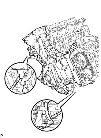 Courtesy of © TOYOTA, LICENSE AGREEMENT TMS1002 Courtesy of © TOYOTA, LICENSE AGREEMENT TMS1002
|
HINT:
Tape the screwdriver tip before use.
NOTE:
Be careful not to damage the cylinder head and cylinder block contact surfaces of the timing chain or belt cover sub-assembly.
- Remove the oil pump gasket from the cylinder block.
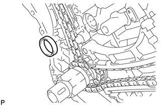 Courtesy of © TOYOTA, LICENSE AGREEMENT TMS1002 Courtesy of © TOYOTA, LICENSE AGREEMENT TMS1002
|
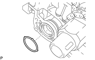
- Remove the O-ring from the oil pan sub-assembly.
 Courtesy of © TOYOTA, LICENSE AGREEMENT TMS1002 Courtesy of © TOYOTA, LICENSE AGREEMENT TMS1002
|
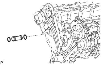
- REMOVE INLET WATER PIPE
- Remove the inlet water pipe from the No. 1 heat exchanger cover.
 Courtesy of © TOYOTA, LICENSE AGREEMENT TMS1002 Courtesy of © TOYOTA, LICENSE AGREEMENT TMS1002
|
- Remove the 2 O-rings from the inlet water pipe.