Timing Chain Removal/Installation - 4.0L
- Remove the valve covers. See VALVE COVER - RH REMOVAL/INSTALLATION - 4.0L and VALVE COVER - LH REMOVAL/INSTALLATION - 4.0L .
- Remove the intake manifold. See INTAKE MANIFOLD REMOVAL/INSTALLATION - 4.0L
.
- Remove the fuel supply manifold. See FUEL INJECTION SUPPLY MANIFOLD AND FUEL INJECTOR - 2.3L REMOVAL/INSTALLATION
.
- Remove the accessory drive belt. See DRIVE BELT REMOVAL/INSTALLATION - 4.0L .
- Remove the thermostat housing. See THERMOSTAT REMOVAL/INSTALLATION - 4.0L
.
- Remove the valve tappets. See VALVE TAPPET REMOVAL/INSTALLATION - 4.0L .
NOTE:
- You must re-time the LH and RH camshafts when either camshaft is disturbed.
- Turn the crankshaft clockwise to position the number one cylinder at TDC using the special tool.
NOTE:
- The special tool must be installed on the damper and should contact the engine block, this positions the engine at top dead center (TDC).
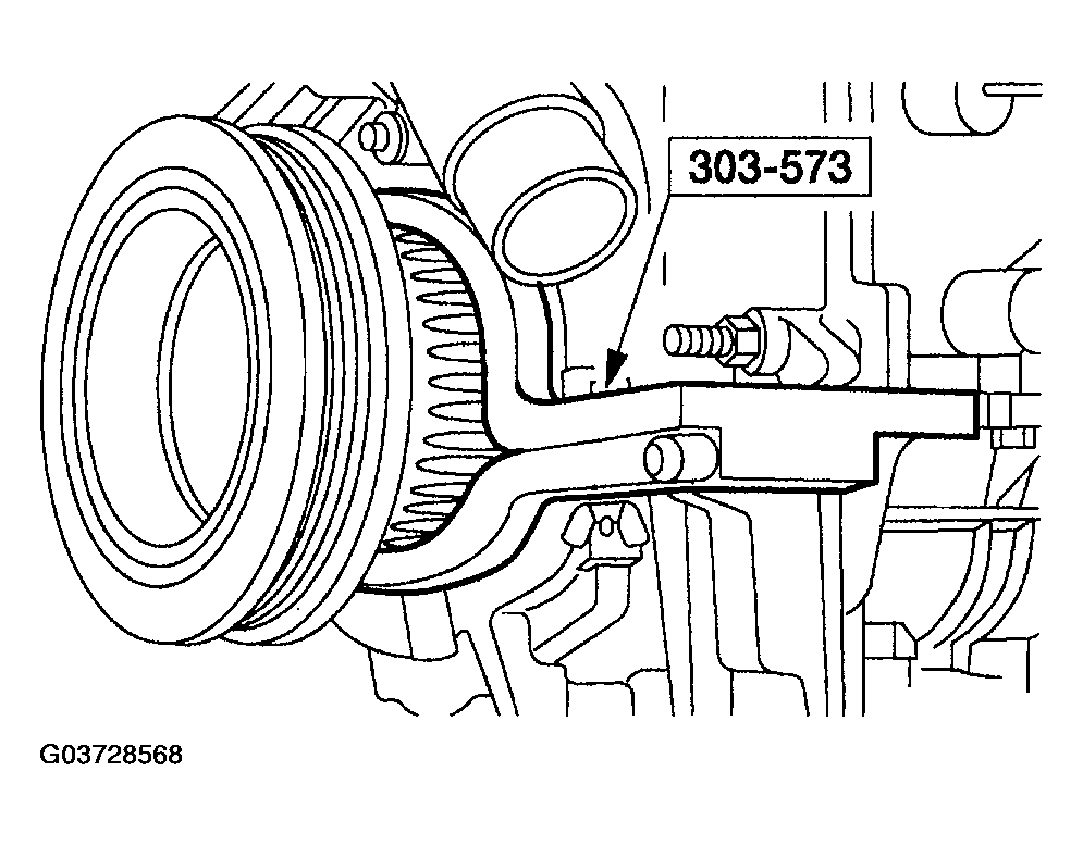 Courtesy of MAZDA MOTORS CORP.
- Install the special tool with the adapter 303-575 or equivalent.
CAUTION:
- The right-hand camshaft sprocket bolt is a left-hand threaded bolt.
- Using the special tool, loosen the RH camshaft sprocket bolt.
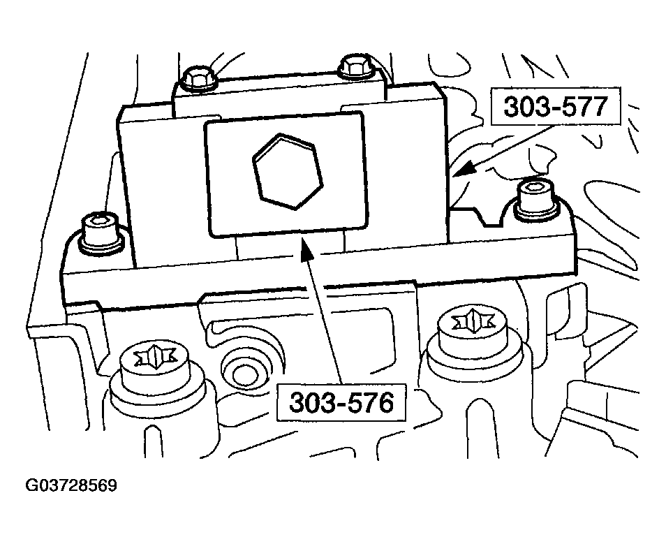 Courtesy of MAZDA MOTORS CORP.
NOTE:
- The camshaft timing slots are off-center.
- Position the camshaft timing slots below the center-line of the camshaft to correctly fit the special tools and install the special tools on the front of the RH cylinder head.
- Raise and support the vehicle. See LIFTING
.
- Remove the RH wheel and tire.
- Remove the RH lower splash shield.
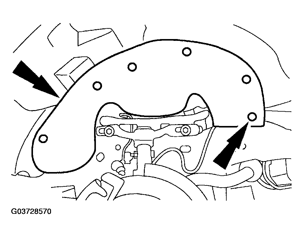 Courtesy of MAZDA MOTORS CORP.
- Remove the RH camshaft tensioner.
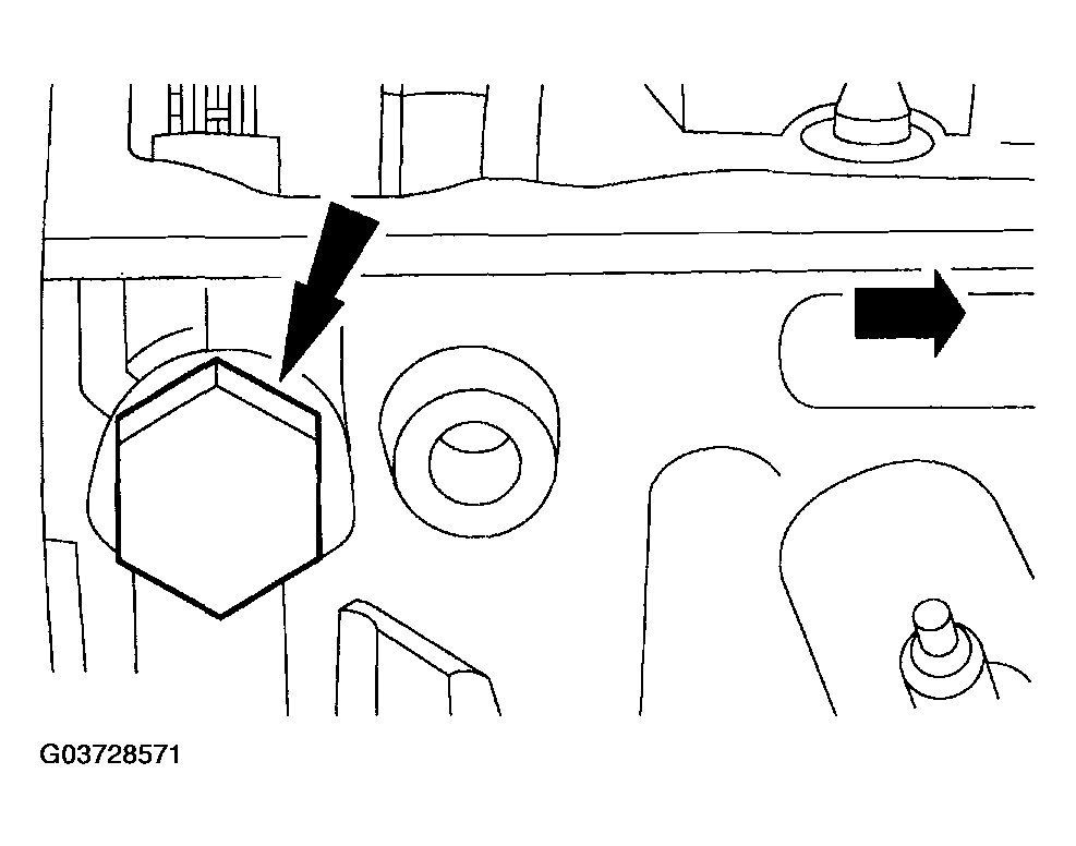 Courtesy of MAZDA MOTORS CORP.
- Lower the vehicle.
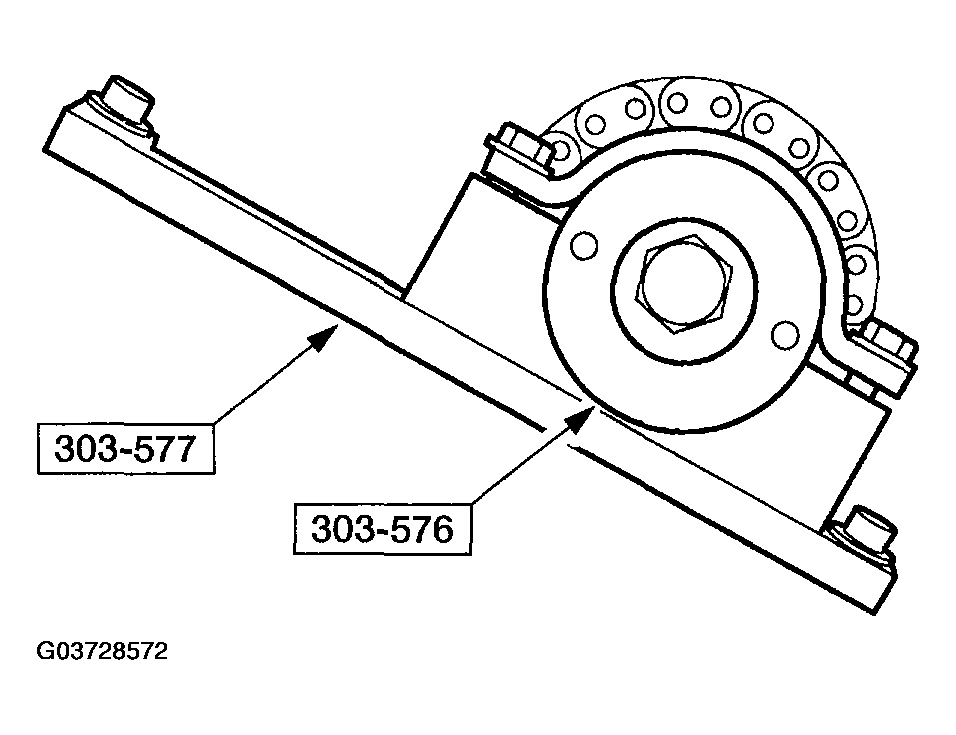
NOTE:
- Leave the top two special tool clamp bolts loose.
- Install the special tools on the rear of the RH cylinder head.
 Courtesy of MAZDA MOTORS CORP.
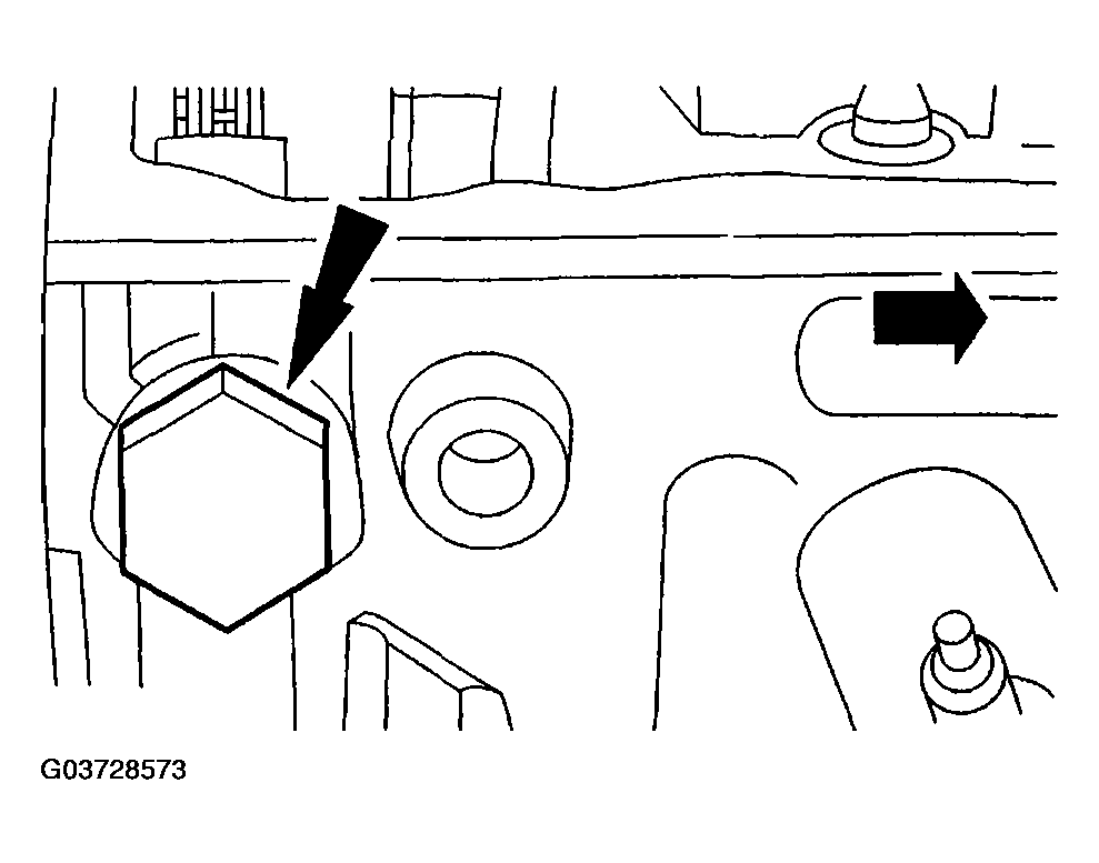
- Install the RH camshaft chain tensioner, but do not tighten.
 Courtesy of MAZDA MOTORS CORP.
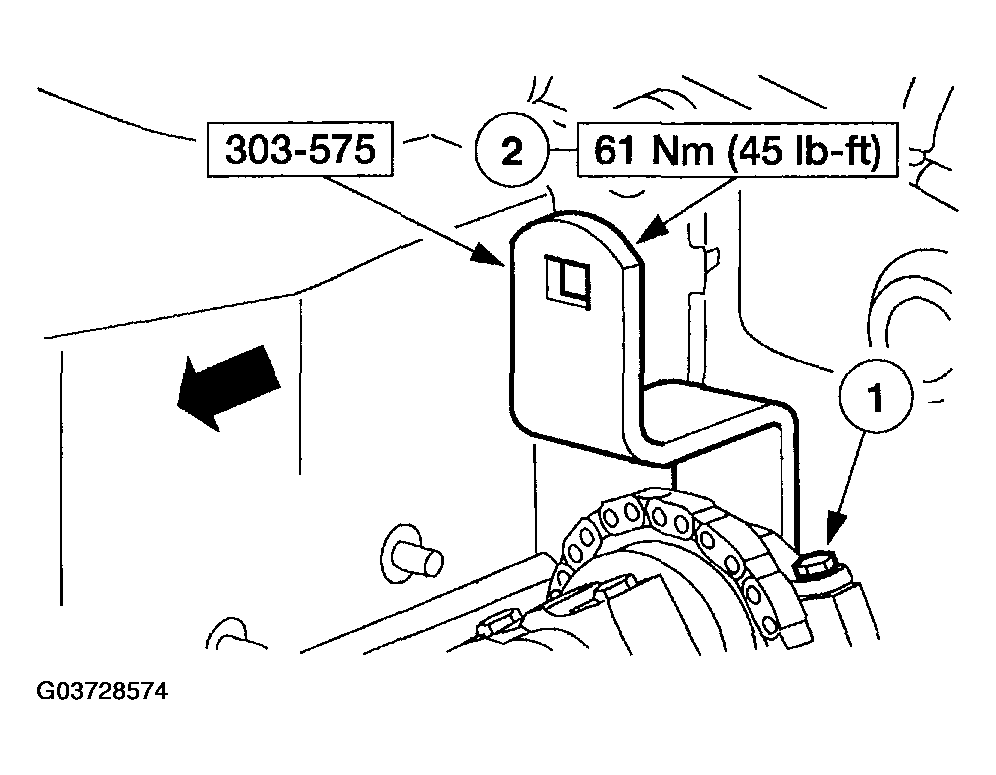
CAUTION:
- The right-hand camshaft sprocket bolt is a left-hand threaded bolt.
- Tighten the bolts.
- Tighten the top of two clamp bolts of the special tool to 10 N.m (89 lb-in).
- Tighten the camshaft bolt.
 Courtesy of MAZDA MOTORS CORP.
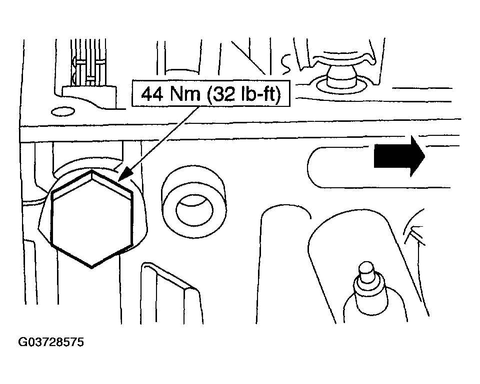
- Tighten the RH camshaft tensioner.
 Courtesy of MAZDA MOTORS CORP.
- Raise the vehicle.
- Install the RH lower splash shield.
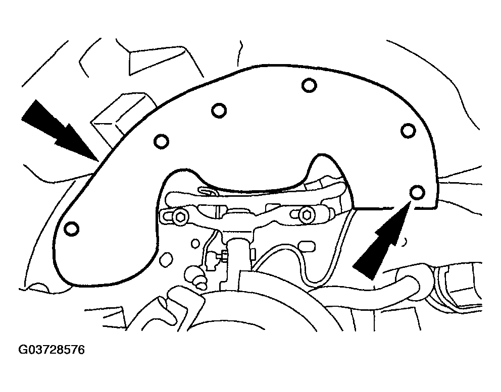 Courtesy of MAZDA MOTORS CORP.
- Install the RH wheel and tire.
- Lower the vehicle.
- Remove the special tools from the RH cylinder head.
- Remove the LH camshaft tensioner.
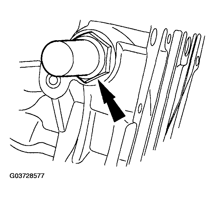 Courtesy of MAZDA MOTORS CORP.
- Install the special tools on the front of the LH cylinder head and tighten the top two clamp bolts to 10 N.m (89 lb-in).
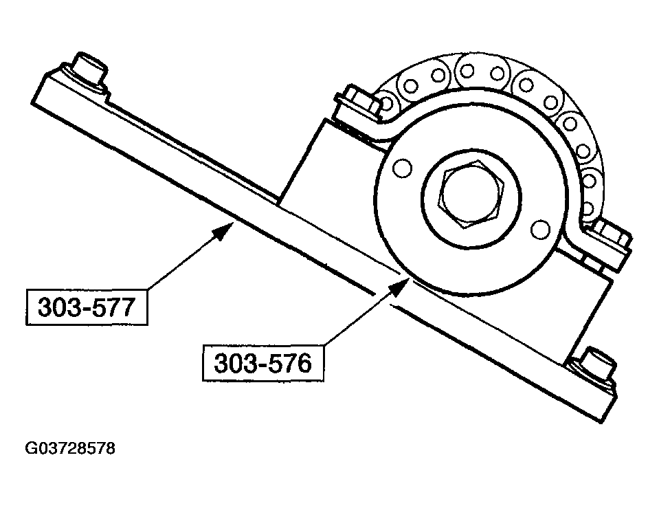 Courtesy of MAZDA MOTORS CORP.
- Loosen the LH camshaft sprocket bolt.
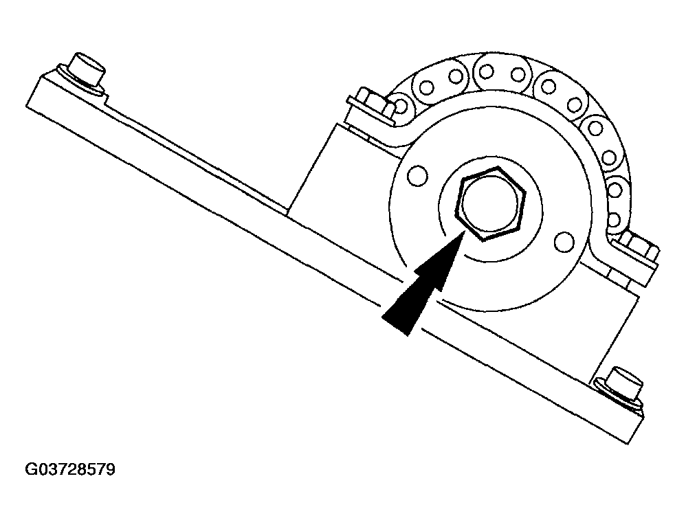 Courtesy of MAZDA MOTORS CORP.
- Loosen the top two clamp bolts on the special tool to allow the camshaft sprocket to rotate freely.
NOTE:
- The camshaft timing slots are off-center.
- Position the camshaft timing slots below the center-line of the camshaft to correctly fit the special tools, and install the special tools on the rear of the LH cylinder head.
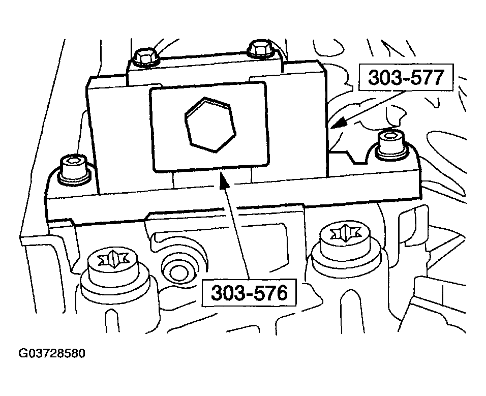 Courtesy of MAZDA MOTORS CORP.
- Install the LH camshaft chain tensioner, but do not tighten.
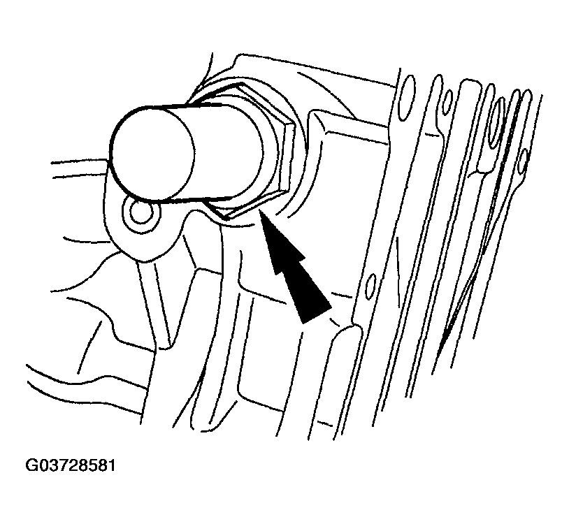 Courtesy of MAZDA MOTORS CORP.
- Tighten the bolts.
- Tighten the top two clamp bolts of the special tool to 10 N.m (89 lb-in).
- Tighten the camshaft bolt.
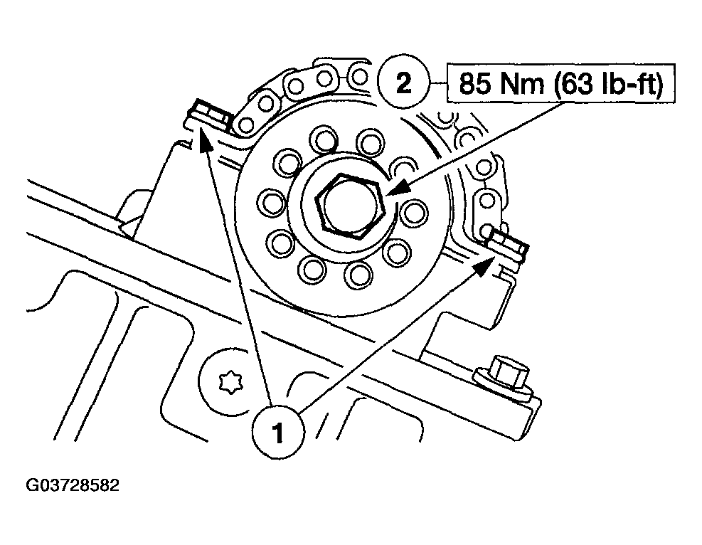 Courtesy of MAZDA MOTORS CORP.
- Tighten the LH camshaft tensioner.
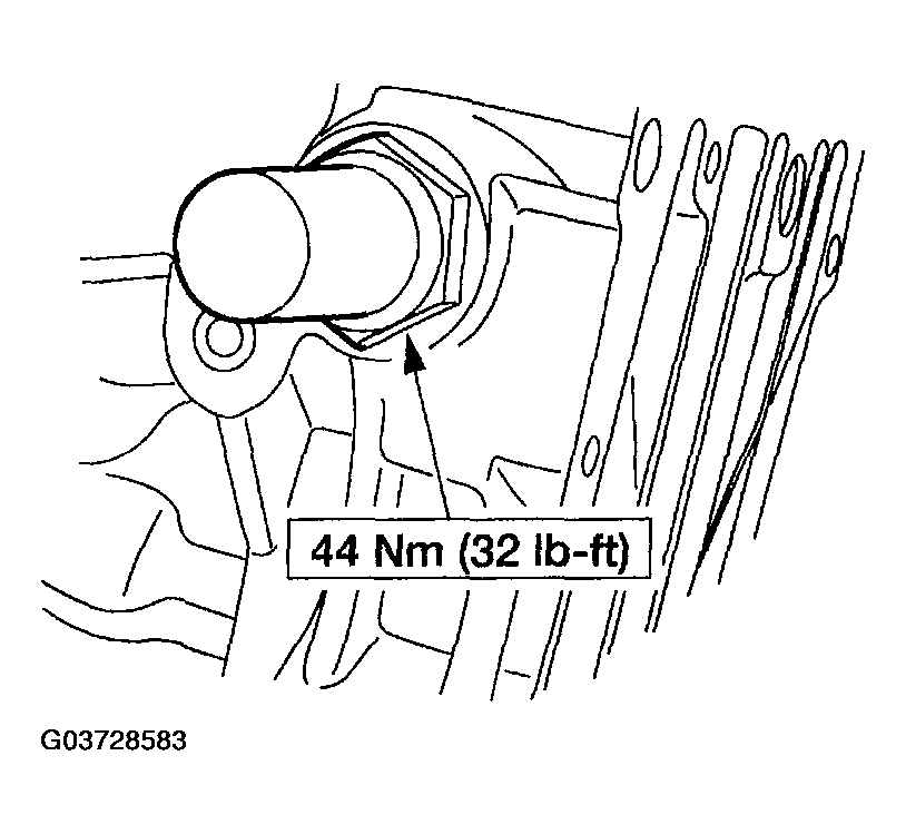 Courtesy of MAZDA MOTORS CORP.
- Remove all of the special tools.
- Install the valve tappets. See VALVE TAPPET REMOVAL/INSTALLATION - 4.0L .
- Install the thermostat housing. See THERMOSTAT REMOVAL/INSTALLATION - 4.0L
.
- Install the accessory drive belt. See DRIVE BELT REMOVAL/INSTALLATION - 4.0L .
- Install the fuel supply manifold. See FUEL INJECTION SUPPLY MANIFOLD AND FUEL INJECTOR - 2.3L REMOVAL/INSTALLATION
.
- Install the intake manifold. See INTAKE MANIFOLD REMOVAL/INSTALLATION - 4.0L
.
- Install the valve covers. See VALVE COVER - RH REMOVAL/INSTALLATION - 4.0L and VALVE COVER - LH REMOVAL/INSTALLATION - 4.0L .