- Install the cylinder head assembly parts:
- Cut the 2 elastomer sealing lips (1) from engine front cover gasket.
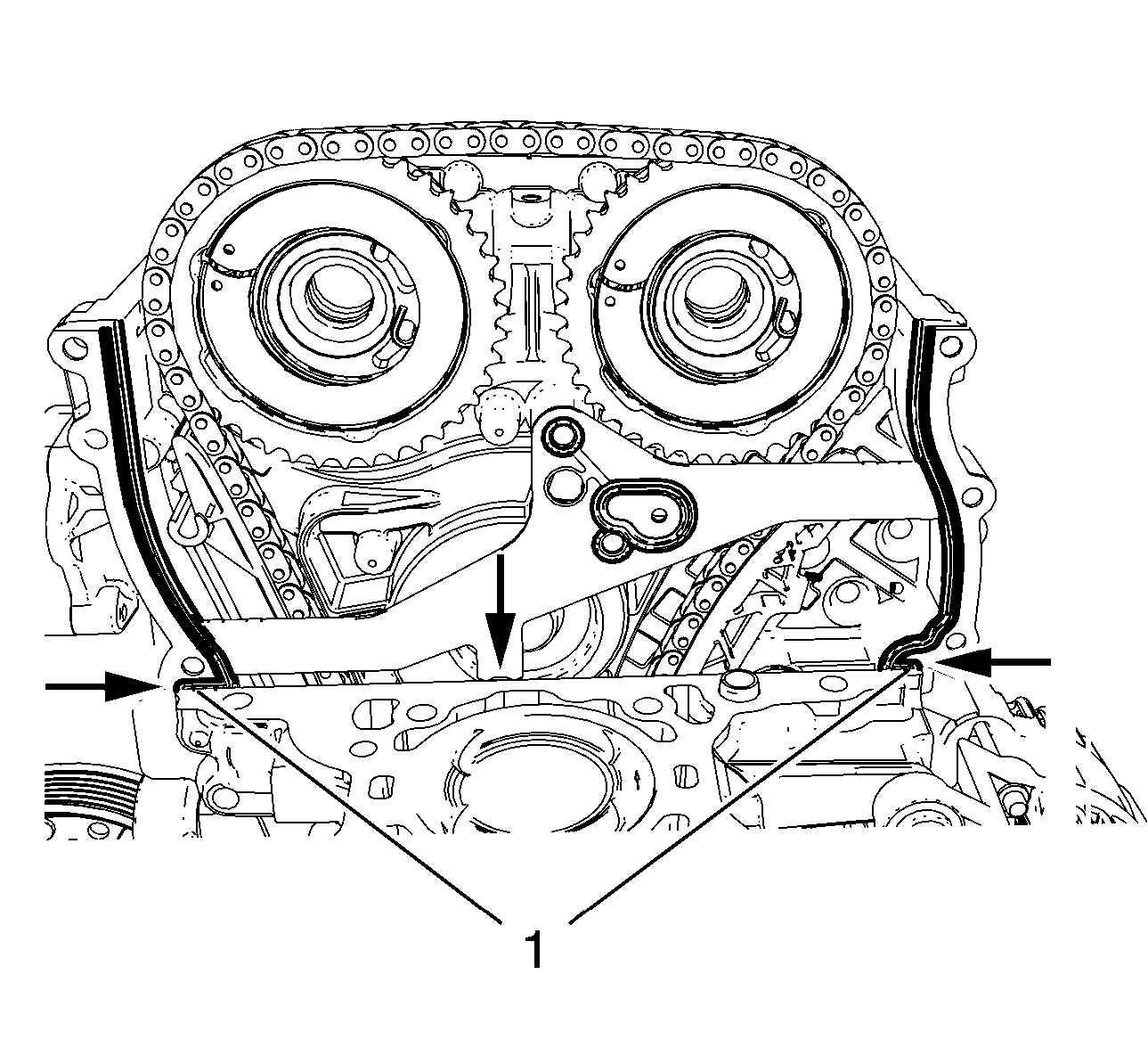 Courtesy of GENERAL MOTORS COMPANY
- Bend down the engine front cover gasket at the predetermined breaking points (arrows).
- Clean sealing surfaces of engine front cover and engine block from grease and old gasket material.
- Inspect cylinder block and cylinder head for flatness. Refer to Cylinder Head Cleaning and Inspection and Engine Block Cleaning and Inspection .
- Apply sealing compound to the shown areas (1). Refer to Adhesives, Fluids, Lubricants and Sealers .
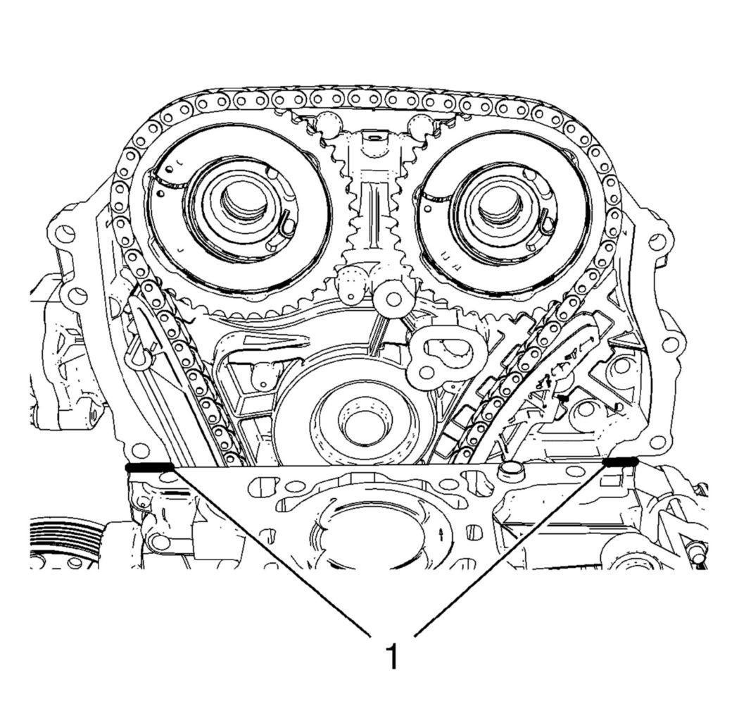 Courtesy of GENERAL MOTORS COMPANY
NOTE:
The thickness of the sealing bead should be 2 mm (0.0787 in).
- Install the cylinder head gasket to engine block.
NOTE:
Mind the marking on the cylinder head gasket for top side.
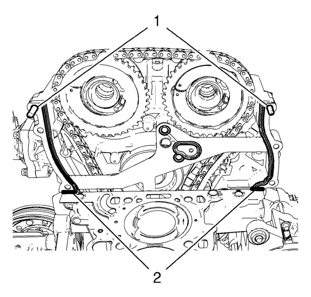
- Install 2 engine front cover bolts (1) in order to guide the NEW upper engine front cover gasket.
 Courtesy of GENERAL MOTORS COMPANY
- Install the NEW upper engine front cover gasket.
- Apply sealing compound to the shown areas (2). The thickness of the sealing bead should be 2 mm (0.0787 in).
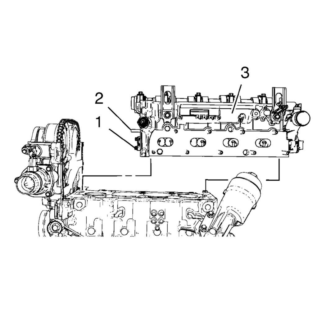
- Install the cylinder head (3).
 Courtesy of GENERAL MOTORS COMPANY
NOTE:
- A second technician is required. Guide the timing chain guide pin (2) to the timing chain guide and the timing chain tensioner (1) with the installed fixing pin through the timing chain tensioner plug bore in engine front cover.
- Check the proper seat of the 2 cylinder head guide sleeves.
- To install the 2 cylinder head bolts at the transmission side, remove and reinstall the EN-953-A
fixing tool.
- Loosely install 12 NEW cylinder head bolts.
- Adjust the cylinder head to the engine front cover. Use a rubber mallet.
 Courtesy of GENERAL MOTORS COMPANY
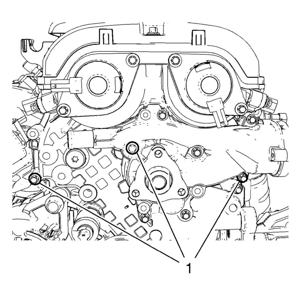
- Locate the engine front cover to cylinder head by installing 3 bolts (1).
- Tighten the 3 bolts (1) to 8 N.m (71 lb in).
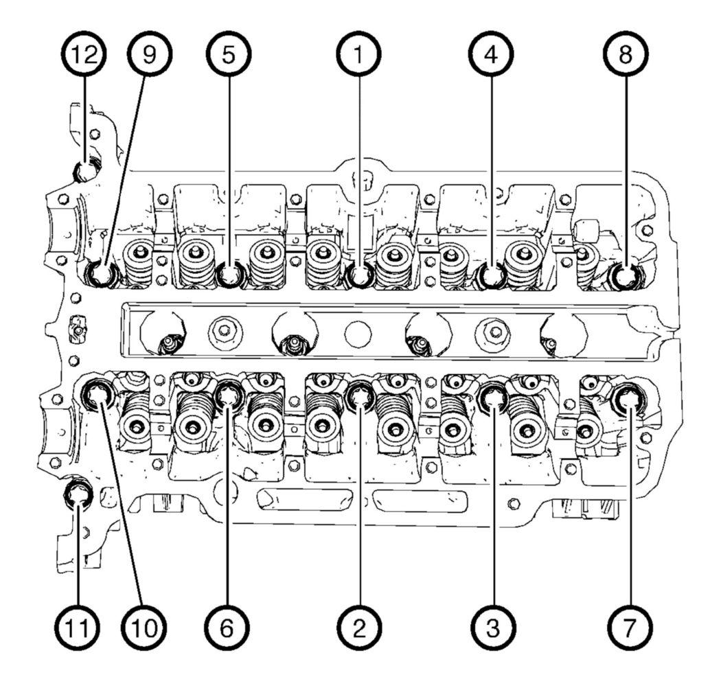
- Tighten the cylinder head bolts in the sequence as shown and in the following order:
 Courtesy of GENERAL MOTORS COMPANY
- Tighten the cylinder head bolts a first pass to 35 N.m (26 lb ft).
- Tighten the cylinder head bolts a final pass to an additional 180 degrees, using EN-470-B
wrench.
- Loosen the 3 bolts from engine front cover.
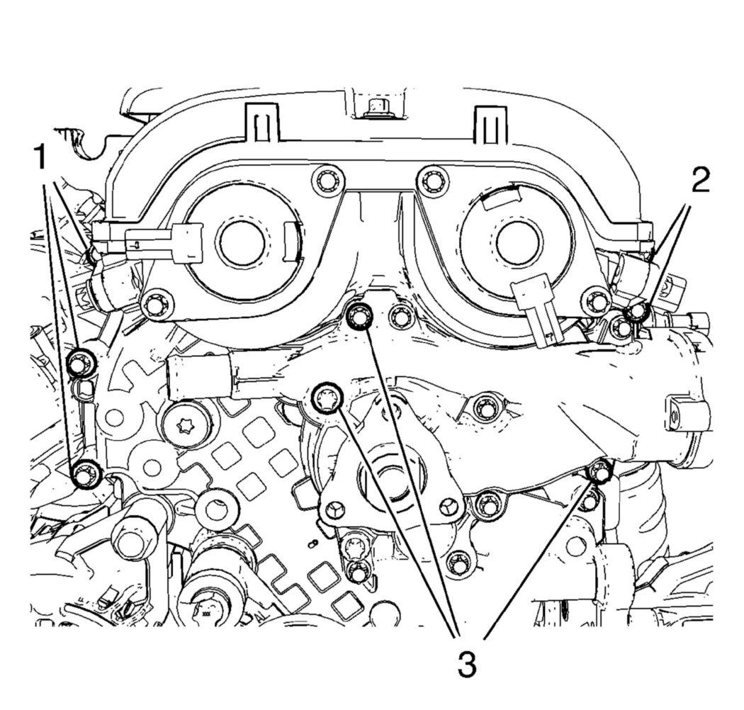
- Install the 5 remaining bolts to engine front cover and water pump.
 Courtesy of GENERAL MOTORS COMPANY
- Tighten the 5 engine front cover bolts (1, 2) to 8 N.m (71 lb in).
- Tighten the 3 water pump bolts (3) to 8 N.m (71 lb in).
- Remove the engine mount bracket. Refer to Engine Mount Bracket Replacement - Right Side .
- Install the water pump pulley. Refer to Water Pump Pulley Installation .
- Install the drive belt. Refer to Drive Belt Replacement .
- Install engine mount bracket. Refer to Engine Mount Bracket Replacement - Right Side .
- Install the engine mount. Refer to Engine Mount Replacement - Right Side .
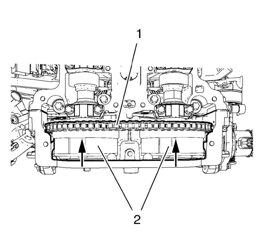
- Install the 2 camshaft sprockets (2) along with the timing chain (1).
 Courtesy of GENERAL MOTORS COMPANY
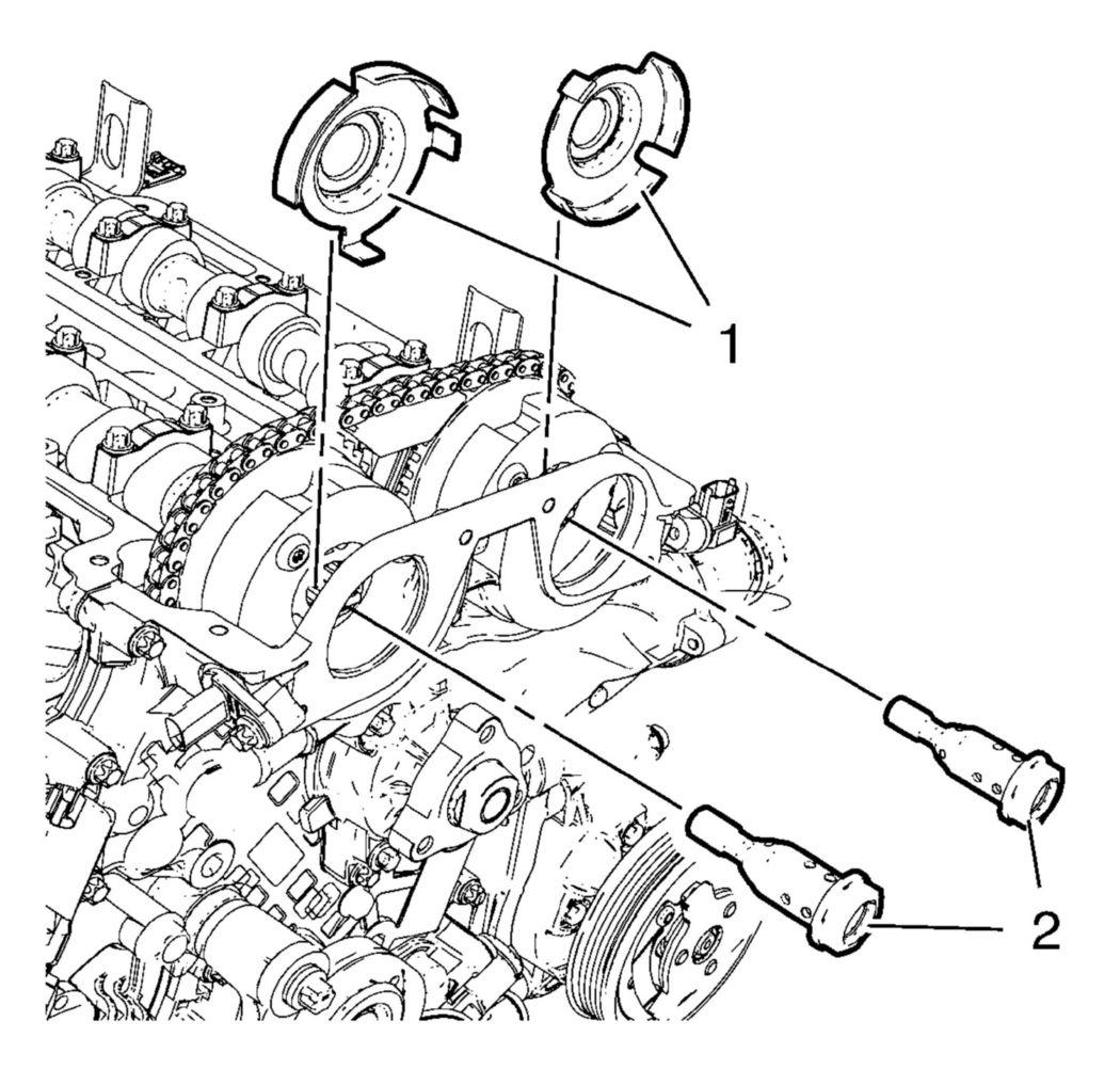
- Install the 2 camshaft position exciter wheels (1) and the 2 NEW camshaft sprocket bolts (2).
 Courtesy of GENERAL MOTORS COMPANY
NOTE:
Camshaft position exciter wheels should stay rotatable.
- Adjust engine to TDC:
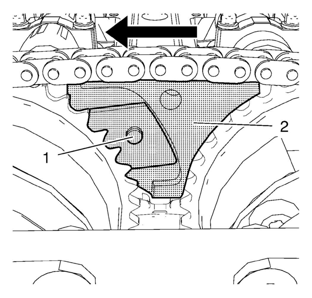
- Install the EN-49977-200
fixing tool (2) and adjust the gearing of the fixing tool so it engages with the intake camshaft sprocket gearing (1).
 Courtesy of GENERAL MOTORS COMPANY
NOTE:
Push the fixing tool in the direction of the arrow to ensure it engages without clearance.
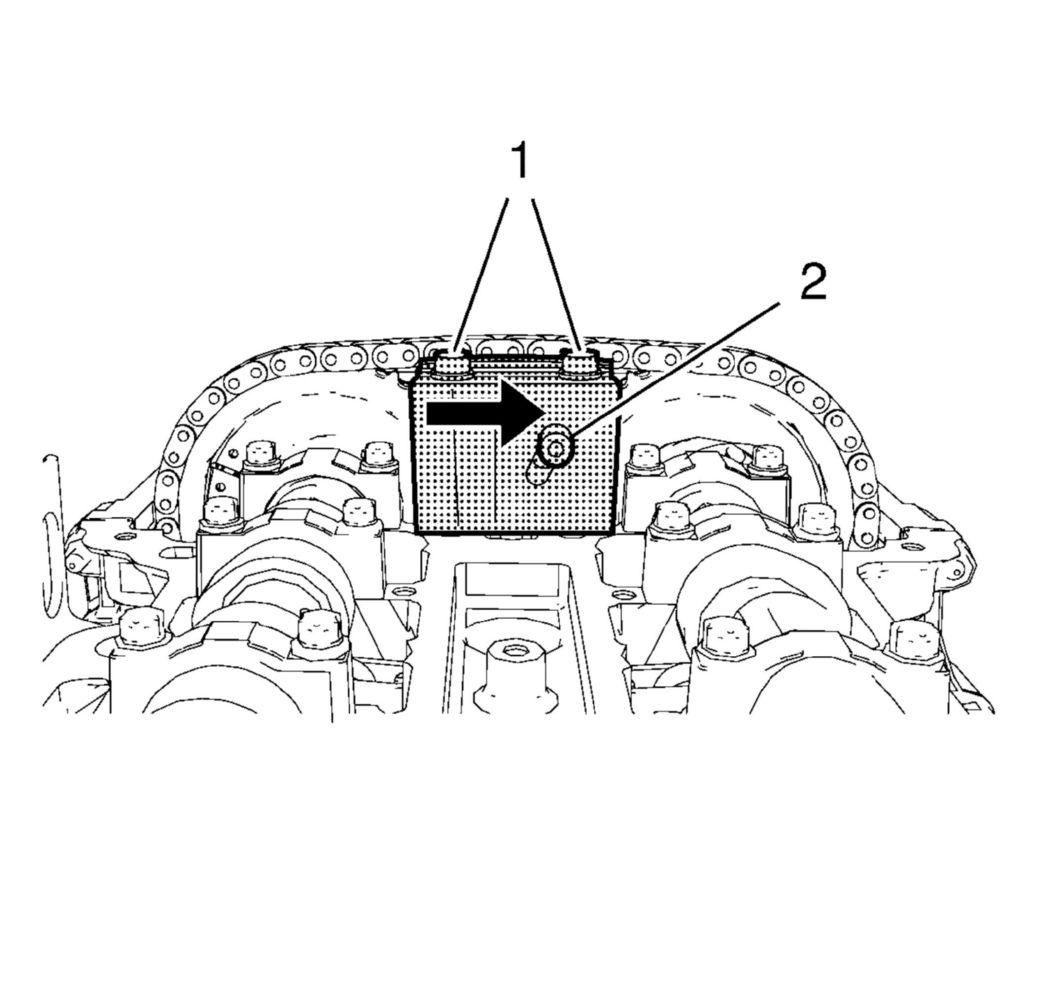
- Tighten the 2 fastening bolts (1) of the EN-49977-200
fixing tool while pushing the fixing tool in direction of the arrow.
 Courtesy of GENERAL MOTORS COMPANY
- Tighten the adjuster bolt (2).
- Install the EN-49977-100
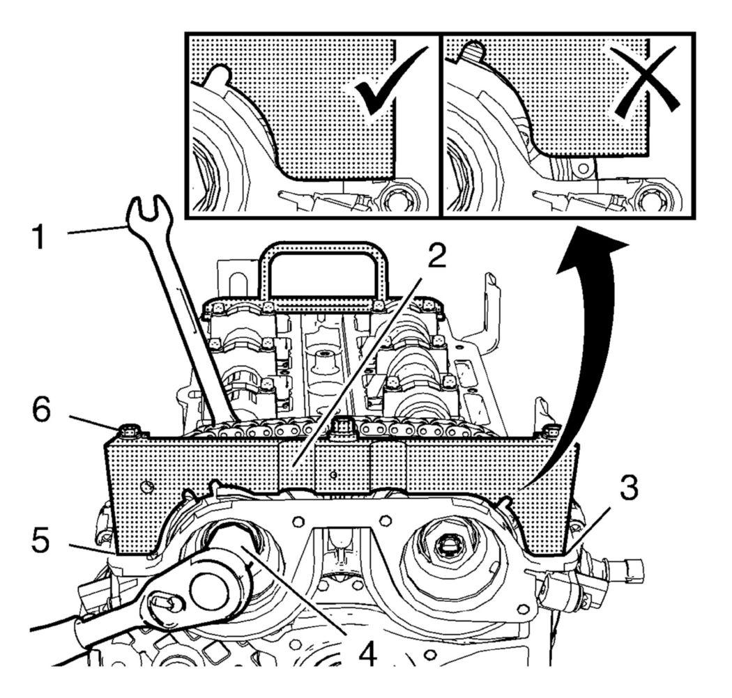
fixation (2) to find and hold the camshaft position exciter wheels in the correct position.
 Courtesy of GENERAL MOTORS COMPANY
NOTE:
A wrong installation position is possible. Make sure that the fixation tool is installed without clearance to the cylinder head in areas (3) and (5).
- Tighten the 2 fastening bolts (6) of the EN-49977-100
fixation.
- Tighten the intake camshaft sprocket bolt (4) while holding the hexagon (1) of the intake camshaft to 50 N.m (37 lb ft).
- Tighten the intake camshaft sprocket bolt (4) while holding the hexagon (1) of the intake camshaft an additional 60 degrees.
- Tighten the exhaust camshaft sprocket bolt while holding the hexagon of the exhaust camshaft to 50 N.m (37 lb ft).
- Tighten the exhaust camshaft sprocket bolt while holding the hexagon of the exhaust camshaft an additional 60 degrees.
- Remove the EN-49977-100
fixation and the EN-49977-200
fixing tool.
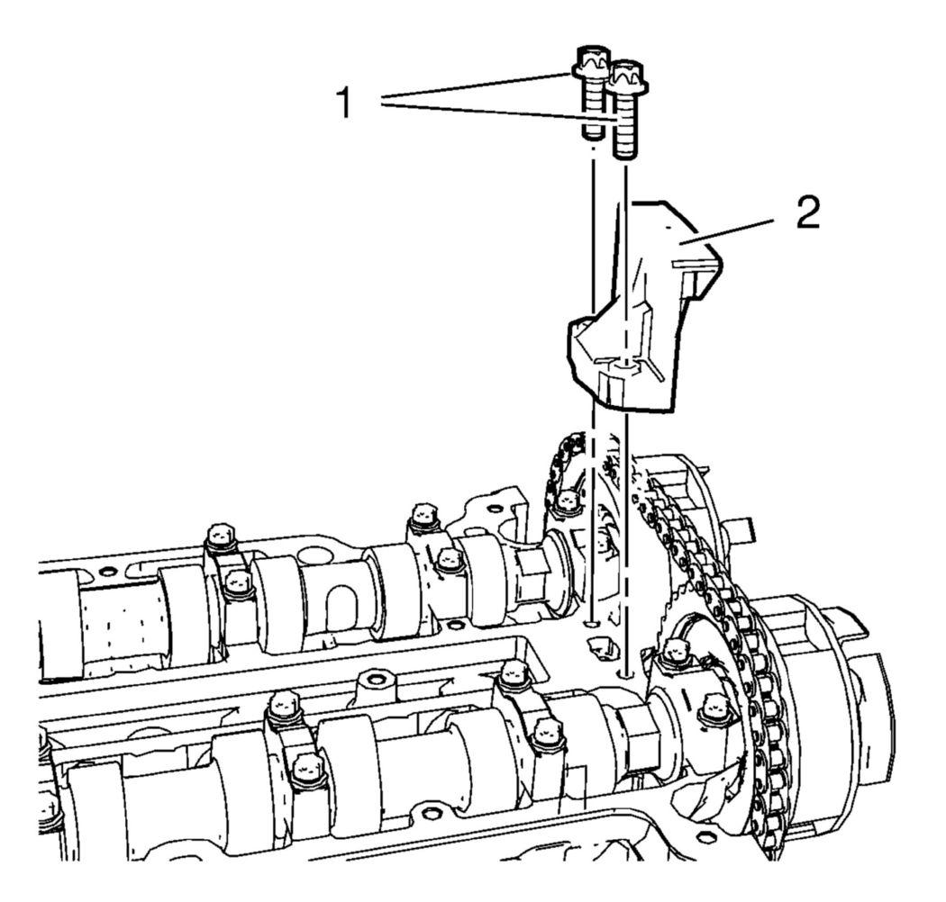
- Install the upper timing chain guide (2).
 Courtesy of GENERAL MOTORS COMPANY
- Install the 2 upper timing chain guide bolts (1) and tighten to 8 N.m (71 lb in).
- Remove the EN-953-A
fixing tool.
- Remove the EN-952
fixing pin.
- Remove the EN-955-10
fixing pin.
- Rotate the crankshaft for 720° and check the engine timing again.
- Check the engine timing again:
- Install the EN-952
fixing pin.
- Install the EN-953-A
fixing tool.
- Install the EN-49977-100
fixation.
- Repeat the adjustment procedure if necessary.
- Install the crankshaft bearing cap tie plate hole plug and seal ring and tighten to 40 N.m (30 lb ft).
- Install the timing chain tensioner plug and tighten to 35 N.m (26 lb ft).
- Install the 2 camshaft position actuator solenoid valves. Refer to Camshaft Position Actuator Solenoid Valve Installation .
- Install the camshaft cover. Refer to Camshaft Cover Replacement .
- Install the ignition coil and connect the ignition coil wiring harness plug. Refer to Ignition Coil Replacement
.
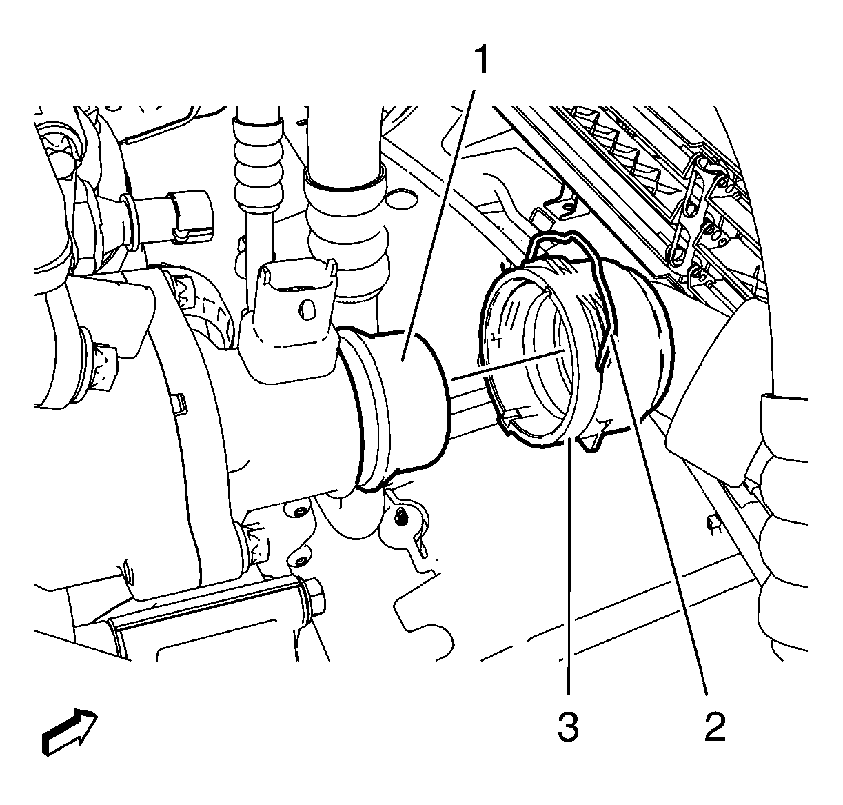
- Connect radiator outlet hose (3) to engine coolant thermostat housing (1). Clip quick connector (2).
 Courtesy of GENERAL MOTORS COMPANY
- Install the ground cable (1) and the ground cable bolt (2) and tighten to 20 N.m (15 lb ft).
 Courtesy of GENERAL MOTORS COMPANY
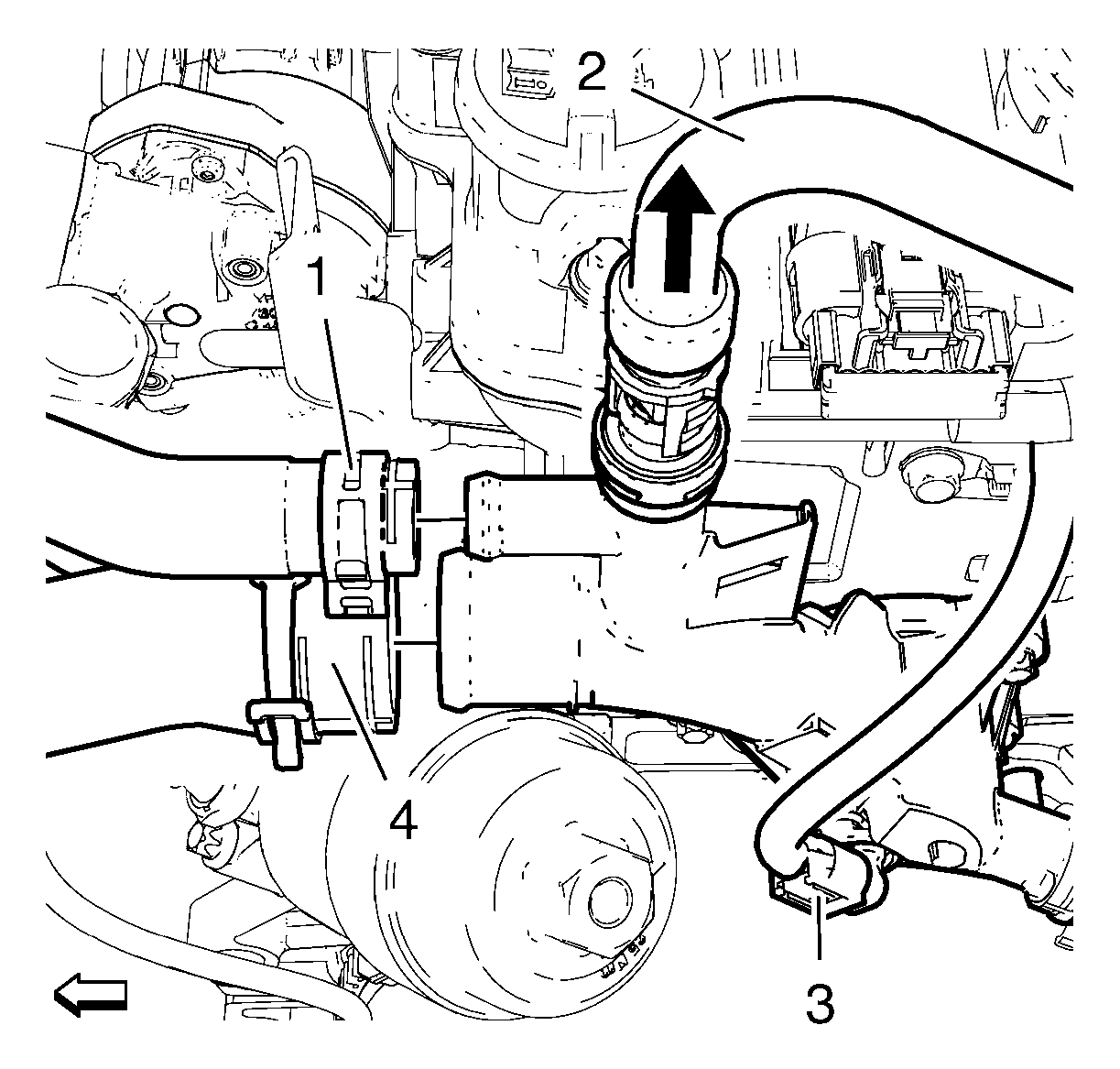
- Install the radiator inlet hose (4) and the radiator inlet hose clamp to the water outlet.
 Courtesy of GENERAL MOTORS COMPANY
- Install the oil cooler inlet hose (1) and the oil cooler inlet hose clamp to the water outlet.
- Connect the engine coolant air bleed hose (2) to the water outlet.
- Connect the engine coolant temperature sensor wiring harness plug (3).
- Install the heater inlet hose to the water outlet. Refer to Heater Inlet Hose Replacement (1.4L LUV)
.
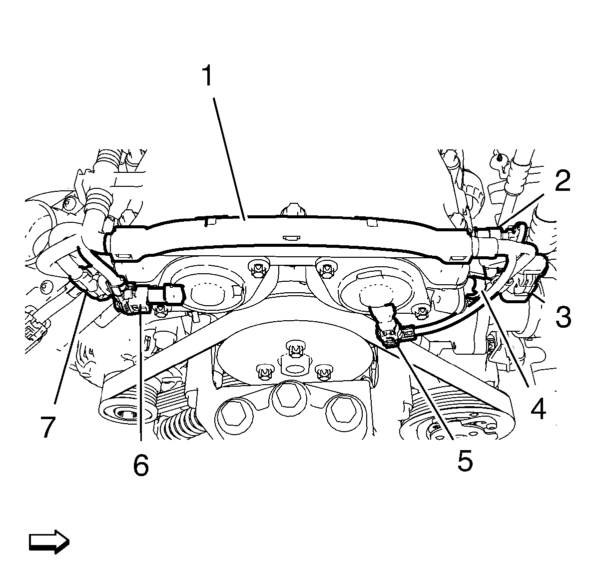
- Install the engine control module wiring harness to the camshaft cover:
 Courtesy of GENERAL MOTORS COMPANY
- Connect the engine coolant temperature sensor wiring harness plug (3).
- Connect the exhaust camshaft position actuator solenoid valve wiring harness plug (5).
- Connect the exhaust camshaft position sensor wiring harness plug (4).
- Connect the intake camshaft position actuator solenoid valve wiring harness plug (6).
- Connect the intake camshaft position sensor wiring harness plug (7).
- Install the turbocharger. Refer to Turbocharger Replacement .
- Install the intake manifold. Refer to Intake Manifold Replacement .
- Install the air cleaner assembly in compound with the air cleaner outlet duct. Refer to Air Cleaner Assembly Replacement
and Air Cleaner Outlet Duct Replacement
.
- Install the engine sight shield.
- Connect battery negative cable. Refer to Battery Negative Cable Disconnection and Connection
.
- Fill coolant fluid. Refer to Cooling System Draining and Filling (GE-47716 Fill)
and Cooling System Draining and Filling (Static Fill)
.
- Check and correct engine oil.