- REMOVE DRIVE SHAFT BEARING BRACKET
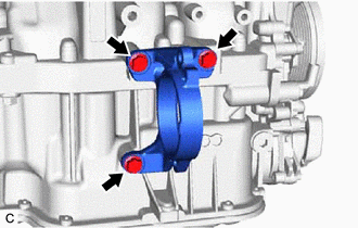
- for 2WD:
- Remove the 3 bolts and drive shaft bearing bracket.
 Courtesy of © TOYOTA, LICENSE AGREEMENT TMS1002 Courtesy of © TOYOTA, LICENSE AGREEMENT TMS1002
|
- for AWD:
- Remove the 3 bolts and drive shaft bearing bracket.
 Courtesy of © TOYOTA, LICENSE AGREEMENT TMS1002 Courtesy of © TOYOTA, LICENSE AGREEMENT TMS1002
|
- REMOVE V-RIBBED BELT
Refer to PROCEDURE - Step 5
- REMOVE GENERATOR ASSEMBLY
Refer to PROCEDURE - Step 7
- REMOVE COMPRESSOR ASSEMBLY WITH PULLEY
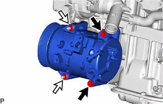
- for Type A:
- Remove the 2 bolts and 2 nuts.
 Courtesy of © TOYOTA, LICENSE AGREEMENT TMS1002 Courtesy of © TOYOTA, LICENSE AGREEMENT TMS1002
|
 |
Bolt |
 |
Nut |
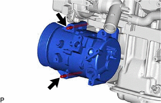
- Using an E8 "TORX" socket wrench, remove the 2 stud bolts and compressor assembly with pulley.
 Courtesy of © TOYOTA, LICENSE AGREEMENT TMS1002 Courtesy of © TOYOTA, LICENSE AGREEMENT TMS1002
|
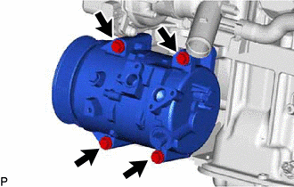
- for Type B:
- Remove the 4 bolts and compressor assembly with pulley.
 Courtesy of © TOYOTA, LICENSE AGREEMENT TMS1002 Courtesy of © TOYOTA, LICENSE AGREEMENT TMS1002
|
- REMOVE NO. 2 ENGINE COVER
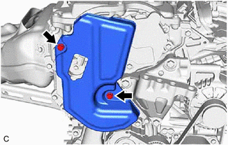
- Remove the 2 bolts and No. 2 engine cover from the No. 2 timing gear cover assembly.
 Courtesy of © TOYOTA, LICENSE AGREEMENT TMS1002 Courtesy of © TOYOTA, LICENSE AGREEMENT TMS1002
|
- REMOVE V-RIBBED BELT TENSIONER ASSEMBLY
NOTE:
- Do not apply or add any oil or grease to the belt tensioner to prevent abnormal noises from the belt tensioner pulley, belt squealing, etc.
- Do not allow oil or grease to adhere to the moving parts of the belt tensioner, as this may cause malfunctions.
 Courtesy of © TOYOTA, LICENSE AGREEMENT TMS1002 Courtesy of © TOYOTA, LICENSE AGREEMENT TMS1002
|
If oil or grease is on the location indicated by the arrow, replace the V-ribbed belt tensioner assembly.
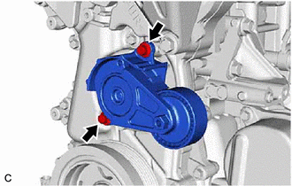
- Remove the 2 bolts and V-ribbed belt tensioner assembly from the No. 2 timing gear cover assembly.
 Courtesy of © TOYOTA, LICENSE AGREEMENT TMS1002 Courtesy of © TOYOTA, LICENSE AGREEMENT TMS1002
|
- REMOVE NO. 2 TIMING CHAIN COVER INSULATOR
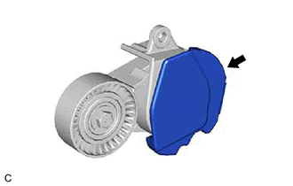
- Remove the No. 2 timing chain cover insulator from the V-ribbed belt tensioner assembly.
 Courtesy of © TOYOTA, LICENSE AGREEMENT TMS1002 Courtesy of © TOYOTA, LICENSE AGREEMENT TMS1002
|
- REMOVE TIMING GEAR COVER INSULATOR
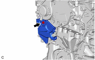
- Using an 8 mm socket wrench, remove the bolt, plate washer and timing gear cover insulator from the No. 2 timing gear cover assembly.
 Courtesy of © TOYOTA, LICENSE AGREEMENT TMS1002 Courtesy of © TOYOTA, LICENSE AGREEMENT TMS1002
|
- REMOVE NO. 3 TIMING CHAIN COVER (w/ Cover)
- Using an 8 mm socket wrench, remove the bolt, plate washer and No. 3 timing chain cover from the No. 2 timing gear cover assembly.
 Courtesy of © TOYOTA, LICENSE AGREEMENT TMS1002 Courtesy of © TOYOTA, LICENSE AGREEMENT TMS1002
|
- REMOVE NO. 2 WATER BY-PASS PIPE SUB-ASSEMBLY
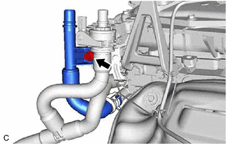
- Slide the clip and disconnect the No. 2 water by-pass pipe sub-assembly from the outlet water by-pass sub-assembly.
 Courtesy of © TOYOTA, LICENSE AGREEMENT TMS1002 Courtesy of © TOYOTA, LICENSE AGREEMENT TMS1002
|
- Remove the bolt and the No. 2 water by-pass pipe sub-assembly.
- REMOVE FLOW SHUTTING VALVE (WATER BY-PASS HOSE ASSEMBLY)
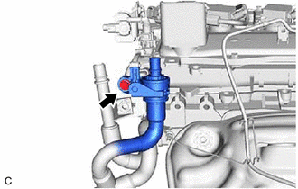
- Remove the bolt to disconnect the flow shutting valve (water by-pass hose assembly).
 Courtesy of © TOYOTA, LICENSE AGREEMENT TMS1002 Courtesy of © TOYOTA, LICENSE AGREEMENT TMS1002
|
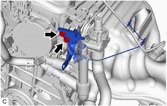
- Remove the 2 bolts and the water hose clamp bracket.
 Courtesy of © TOYOTA, LICENSE AGREEMENT TMS1002 Courtesy of © TOYOTA, LICENSE AGREEMENT TMS1002
|
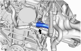
- Slide the clip and remove the flow shutting valve (water by-pass hose assembly) from the water by-pass outlet sub-assembly.
 Courtesy of © TOYOTA, LICENSE AGREEMENT TMS1002 Courtesy of © TOYOTA, LICENSE AGREEMENT TMS1002
|
HINT:
Use a container to catch any engine coolant which flows out of the flow shutting valve (water by-pass hose assembly) and water by-pass outlet sub-assembly.
- REMOVE NO. 1 EXHAUST MANIFOLD HEAT INSULATOR
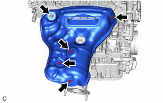
- Remove the 5 bolts and the No. 1 exhaust manifold heat insulator from the exhaust manifold (TWC: Front Catalyst).
 Courtesy of © TOYOTA, LICENSE AGREEMENT TMS1002 Courtesy of © TOYOTA, LICENSE AGREEMENT TMS1002
|
- REMOVE MANIFOLD STAY
Refer to PROCEDURE - Step 18
- REMOVE EXHAUST MANIFOLD (TWC: Front Catalyst)
- Using a 12 mm deep socket wrench, remove the 7 nuts and the exhaust manifold (TWC: Front Catalyst) from the cylinder head sub-assembly.
 Courtesy of © TOYOTA, LICENSE AGREEMENT TMS1002 Courtesy of © TOYOTA, LICENSE AGREEMENT TMS1002
|
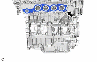
- Remove the exhaust manifold to head gasket from the cylinder head sub-assembly.
 Courtesy of © TOYOTA, LICENSE AGREEMENT TMS1002 Courtesy of © TOYOTA, LICENSE AGREEMENT TMS1002
|
- REMOVE THROTTLE BODY WITH MOTOR ASSEMBLY
Refer to PROCEDURE - Step 4
- REMOVE THROTTLE BODY GASKET
Refer to PROCEDURE - Step 5
- REMOVE EGR COOLER ASSEMBLY
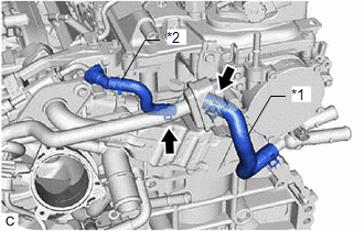
- Disconnect the water hose from the EGR cooler assembly.
 Courtesy of © TOYOTA, LICENSE AGREEMENT TMS1002 Courtesy of © TOYOTA, LICENSE AGREEMENT TMS1002
|
| *1 |
No. 3 Water By-pass Hose |
| *2 |
Water Hose |
- Disconnect the No. 3 water by-pass hose from the EGR cooler assembly.
- Remove the 5 bolts, EGR cooler assembly, EGR cooler gasket and EGR valve gasket.
 Courtesy of © TOYOTA, LICENSE AGREEMENT TMS1002 Courtesy of © TOYOTA, LICENSE AGREEMENT TMS1002
|
- REMOVE NO. 1 EGR COOLER BRACKET
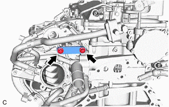
- Remove the 2 bolts and No. 1 EGR cooler bracket from the EGR valve bracket and water outlet.
 Courtesy of © TOYOTA, LICENSE AGREEMENT TMS1002 Courtesy of © TOYOTA, LICENSE AGREEMENT TMS1002
|
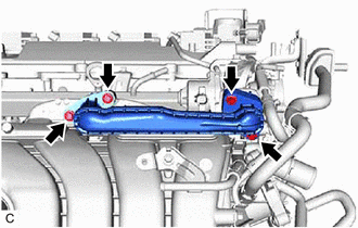
- REMOVE NO. 1 EGR PIPE SUB-ASSEMBLY
- Using an 8 mm socket wrench, remove the 4 bolts, No. 1 EGR pipe sub-assembly, EGR inlet gasket and EGR valve adapter gasket.
 Courtesy of © TOYOTA, LICENSE AGREEMENT TMS1002 Courtesy of © TOYOTA, LICENSE AGREEMENT TMS1002
|
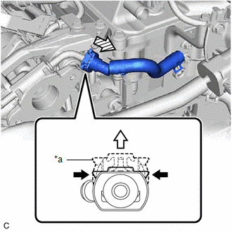
- REMOVE WATER HOSE
- w/ Water Hose Connector:
- Remove the water hose from the EGR valve assembly.
 Courtesy of © TOYOTA, LICENSE AGREEMENT TMS1002 Courtesy of © TOYOTA, LICENSE AGREEMENT TMS1002
|
| *a |
Retainer |
|
Pinch |
|
Pull |
 |
Pull off |
Pinch the retainer of the water hose and then pull out the retainer to disengage the lock claws and pull off the water hose.
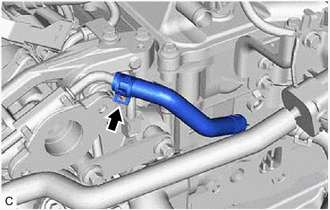
- w/o Water Hose Connector:
- Slide the clip and remove the water hose from the EGR valve assembly.
 Courtesy of © TOYOTA, LICENSE AGREEMENT TMS1002 Courtesy of © TOYOTA, LICENSE AGREEMENT TMS1002
|
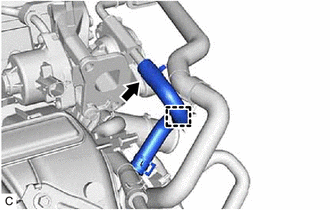
- REMOVE EGR VALVE ASSEMBLY
- Disconnect the clamp.
 Courtesy of © TOYOTA, LICENSE AGREEMENT TMS1002 Courtesy of © TOYOTA, LICENSE AGREEMENT TMS1002
|
- Slide the clip and disconnect the No. 8 water by-pass hose from the EGR valve assembly.
- for EGR Valve Bracket Connection Type:
- Using an 8 mm socket wrench, remove the 2 bolts.
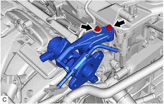 Courtesy of © TOYOTA, LICENSE AGREEMENT TMS1002 Courtesy of © TOYOTA, LICENSE AGREEMENT TMS1002
|
- Remove the EGR valve assembly vertically.
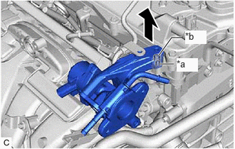 Courtesy of © TOYOTA, LICENSE AGREEMENT TMS1002 Courtesy of © TOYOTA, LICENSE AGREEMENT TMS1002
|
- for Cylinder Head Cover Sub-assembly Connection Type:
- Using an 8 mm socket wrench, remove the bolt.
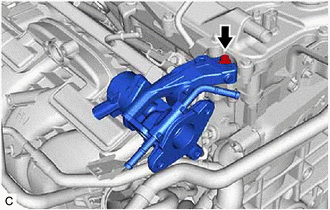 Courtesy of © TOYOTA, LICENSE AGREEMENT TMS1002 Courtesy of © TOYOTA, LICENSE AGREEMENT TMS1002
|
- Remove the EGR valve assembly vertically.
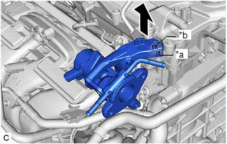 Courtesy of © TOYOTA, LICENSE AGREEMENT TMS1002 Courtesy of © TOYOTA, LICENSE AGREEMENT TMS1002
|
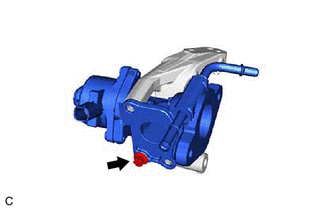
- Using an 8 mm socket wrench, remove the bolt and EGR valve bracket.
 Courtesy of © TOYOTA, LICENSE AGREEMENT TMS1002 Courtesy of © TOYOTA, LICENSE AGREEMENT TMS1002
|
- REMOVE NO. 3 WATER BY-PASS PIPE
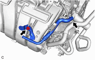
- Using an 8 mm socket wrench, remove the bolt and No. 3 water by-pass pipe from the intake manifold.
 Courtesy of © TOYOTA, LICENSE AGREEMENT TMS1002 Courtesy of © TOYOTA, LICENSE AGREEMENT TMS1002
|
- Slide the clip and disconnect the No. 3 water by-pass pipe from the water outlet.
- REMOVE NO. 2 WATER BY-PASS PIPE
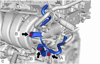
- Remove the bolt (A).
 Courtesy of © TOYOTA, LICENSE AGREEMENT TMS1002 Courtesy of © TOYOTA, LICENSE AGREEMENT TMS1002
|
- Using an 8 mm socket wrench, remove the 2 bolts (B) and No. 2 water by-pass pipe.
- REMOVE INTAKE MANIFOLD
Refer to PROCEDURE - Step 10
- REMOVE NO. 1 INTAKE MANIFOLD TO HEAD GASKET
Refer to PROCEDURE - Step 11
- DISCONNECT FUEL TUBE SUB-ASSEMBLY
Refer to PROCEDURE - Step 5
- REMOVE NO. 1 FUEL PIPE SUB-ASSEMBLY
- for EGR Valve Bracket Connection Type:
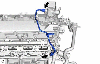
- Using a 17 mm union nut wrench, loosen the 2 union nuts of the No. 1 fuel pipe sub-assembly.
 Courtesy of © TOYOTA, LICENSE AGREEMENT TMS1002 Courtesy of © TOYOTA, LICENSE AGREEMENT TMS1002
|
- for Cylinder Head Cover Sub-assembly Connection Type:
- Using an 8 mm socket wrench, remove the bolt.
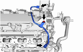 Courtesy of © TOYOTA, LICENSE AGREEMENT TMS1002 Courtesy of © TOYOTA, LICENSE AGREEMENT TMS1002
|
- Using a 17 mm union nut wrench, loosen the 2 union nuts of the No. 1 fuel pipe sub-assembly.
- REMOVE FUEL (ENGINE ROOM SIDE) PUMP ASSEMBLY (for High Pressure)
Refer to PROCEDURE - Step 7
- REMOVE NO. 7 WATER BY-PASS HOSE
- Slide the 2 clips and remove the No. 7 water by-pass hose.
 Courtesy of © TOYOTA, LICENSE AGREEMENT TMS1002 Courtesy of © TOYOTA, LICENSE AGREEMENT TMS1002
|
- REMOVE SENSOR WIRE
- Disconnect the 4 connectors.
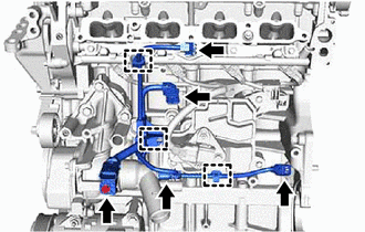 Courtesy of © TOYOTA, LICENSE AGREEMENT TMS1002 Courtesy of © TOYOTA, LICENSE AGREEMENT TMS1002
|
- Disengage the 3 clamps.
- Using an 8 mm socket wrench, remove the bolt and sensor wire from the water inlet with thermostat sub-assembly.
- REMOVE NO. 6 ENGINE WIRE
- Disconnect the 4 connectors.
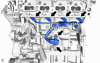 Courtesy of © TOYOTA, LICENSE AGREEMENT TMS1002 Courtesy of © TOYOTA, LICENSE AGREEMENT TMS1002
|
- Disengage the 2 clamps.
- Remove the 2 nuts and No. 6 engine wire from the wire harness clamp bracket.
- REMOVE WIRE HARNESS CLAMP BRACKET
- Using an 8 mm socket wrench, remove the 2 bolts and wire harness clamp bracket from the No. 1 ventilation case.
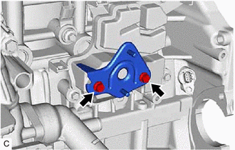 Courtesy of © TOYOTA, LICENSE AGREEMENT TMS1002 Courtesy of © TOYOTA, LICENSE AGREEMENT TMS1002
|
- REMOVE FUEL DELIVERY PIPE WITH SENSOR SUB-ASSEMBLY
Refer to PROCEDURE - Step 7
- REMOVE NO. 1 DELIVERY PIPE SPACER
Refer to PROCEDURE - Step 8
- REMOVE INJECTOR VIBRATION INSULATOR
Refer to PROCEDURE - Step 9
- REMOVE NO. 5 ENGINE WIRE
Refer to PROCEDURE - Step 10
- REMOVE PORT FUEL INJECTOR ASSEMBLY
Refer to PROCEDURE - Step 11
- REMOVE FUEL DELIVERY PIPE
Refer to PROCEDURE - Step 6
- REMOVE DIRECT FUEL INJECTOR ASSEMBLY
Refer to PROCEDURE - Step 7
- REMOVE IGNITION COIL ASSEMBLY
Refer to PROCEDURE - Step 2
- REMOVE ENGINE OIL LEVEL DIPSTICK GUIDE
- Remove the engine oil level dipstick.
- Using an 8 mm socket wrench, remove the bolt and engine oil level dipstick guide from the camshaft housing sub-assembly.
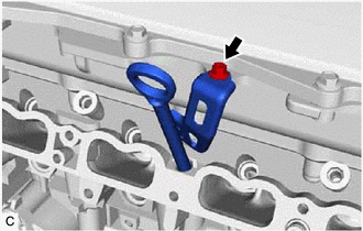 Courtesy of © TOYOTA, LICENSE AGREEMENT TMS1002 Courtesy of © TOYOTA, LICENSE AGREEMENT TMS1002
|
- Remove the O-ring from the engine oil level dipstick guide.
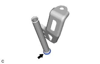 Courtesy of © TOYOTA, LICENSE AGREEMENT TMS1002 Courtesy of © TOYOTA, LICENSE AGREEMENT TMS1002
|
- REMOVE WATER INLET WITH THERMOSTAT SUB-ASSEMBLY
Refer to PROCEDURE - Step 4
- REMOVE ENGINE WATER PUMP ASSEMBLY (WATER INLET HOUSING)
- Remove the 4 bolts, engine water pump assembly (water inlet housing) and gasket from the cylinder block sub-assembly.
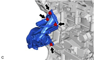 Courtesy of © TOYOTA, LICENSE AGREEMENT TMS1002 Courtesy of © TOYOTA, LICENSE AGREEMENT TMS1002
|
- REMOVE NO. 3 EXHAUST MANIFOLD HEAT INSULATOR
- Remove the bolt and No. 3 exhaust manifold heat insulator from the cylinder block sub-assembly.
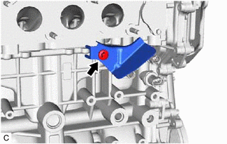 Courtesy of © TOYOTA, LICENSE AGREEMENT TMS1002 Courtesy of © TOYOTA, LICENSE AGREEMENT TMS1002
|
- REMOVE PURGE VALVE (PURGE VSV)
Refer to PROCEDURE - Step 1
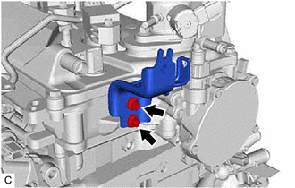
- REMOVE NO. 2 VACUUM SWITCHING VALVE BRACKET
- Using an 8 mm socket wrench, remove the 2 bolts and No. 2 vacuum switching valve bracket from the cylinder head sub-assembly.
 Courtesy of © TOYOTA, LICENSE AGREEMENT TMS1002 Courtesy of © TOYOTA, LICENSE AGREEMENT TMS1002
|