Test M: Brake Warning Never/Always On
- Check brake system warning indicator miniature bulb. Turn key OFF. Remove the instrument cluster. See INSTRUMENT CLUSTER
under REMOVAL & INSTALLATION. Remove the brake system warning indicator miniature bulb. Check the continuity between the terminals of the brake system warning indicator miniature bulb. Does continuity exist? If yes, go to next step. If no, replace the brake system warning indicator miniature bulb.
- Check brake system warning indicator circuit. Turn key OFF. Remove the instrument cluster. Disconnect all of the instrument cluster connectors. Connect a test lamp between terminal No. 2 (Gray/Blue wire) on the instrument cluster connector C268 and terminal No. 10 (Yellow/Purple) wire on the instrument cluster connector C266. Turn key ON. Does the test lamp illuminate? If yes, replace the instrument cluster printed circuit. See INSTRUMENT CLUSTER PRINTED CIRCUIT
under REMOVAL & INSTALLATION. If no, go to next step.
- Check wire between instrument cluster and bulb. Check relay for short. Turn key OFF. Remove the instrument cluster. See INSTRUMENT CLUSTER
under REMOVAL & INSTALLATION. Disconnect the instrument cluster connector C266. Disconnect the brake fluid level switch connector located under the brake fluid reservoir. Remove the bulb check relay from the left hand engine compartment relay panel. Disconnect the top black diode strip at the diode junction box located behind the instrument cluster. See Figure
. Measure the resistance of the Yellow/Purple wire between Pin No. 10 of the instrument cluster connector C266 and ground. Is the resistance greater than 10,000 ohms? If yes, go to next step. If no, service Yellow/Purple wire.
- Check wire between instrument cluster and bulb check relay for open. Turn key OFF. Remove the instrument cluster. See INSTRUMENT CLUSTER
under REMOVAL & INSTALLATION. Disconnect the instrument cluster connector C266. Remove the bulb check relay. See COMPONENT LOCATIONS
. Measure the resistance of the Yellow/Purple wire between the bulb check relay connector and Pin No. 10 of the instrument cluster connector C266. See Fig 1
and WIRING DIAGRAMS
. Is the resistance less than 5 ohms? If yes, go to next step. If no, service Yellow/Purple wire.
- Check relay coil fuse. Check the 10A RLY COIL fuse located in the interior fuse junction panel. Is the fuse okay? If yes, go to step 8
. If no, go to next step.
- Check system. Turn key OFF. Replace the 10A RLY COIL fuse. Turn key ON. Inspect the fuse. Does the fuse fail again? If yes, go to next step. If no, go to step 8
.
- Check for short between interior fuse junction panel and bulb check relay. Turn key OFF. Remove the 10A RLY COIL fuse. Remove the bulb check relay. Measure the resistance of the Blue wire between the right terminal of the 10A RLY COIL fuse and ground. See WIRING DIAGRAMS
. Is the resistance less than 5 ohms? If yes, service Blue wire. If no, replace the 10A RLY COIL fuse and go to next step.
- Check power supply to bulb check relay. Turn key OFF. Remove the bulb check relay. Turn key ON. Measure the voltage on the Blue wire at the bulb check relay connector. Is the voltage greater than 10 volts? See WIRING DIAGRAMS
. If yes, go to next step. If no, service the Blue wire between the interior fuse junction panel and the bulb check relay.
- Check wire between bulb check relay and diode junction box. Turn key OFF. Remove the instrument cluster. See INSTRUMENT CLUSTER
under REMOVAL & INSTALLATION. Remove the bulb check relay. Disconnect the top black diode strip at the diode junction box located behind the instrument cluster. See COMPONENT LOCATIONS
. Measure the resistance of the Blue/Yellow wire between the bulb check relay connector and Pin No. 6 of the diode junction box connector. See WIRING DIAGRAMS
for connector identification. Is the resistance less than 5 ohms? If yes, go to next step. If no, service Blue/Yellow wire.
- Inspect bulb check relay ground. Turn key OFF. Remove the bulb check relay. Measure the resistance of the Black wire between the bulb check relay connector and ground. Is the resistance less than 5 ohms? If yes, go to next step. If no, service Black wire. See WIRING DIAGRAMS
.
- Inspect bulb check relay. Turn key OFF. Remove the bulb check relay. Using a jumper, connect terminal No. 1 (Blue/Yellow wire) on the bulb check relay to the battery positive terminal. See Fig 2
. Measure resistance between terminal No. 5 (Black) wire and terminal No. 3 (Yellow/Purple) wire on the bulb check relay. See WIRING DIAGRAMS
. With terminal No. 2 (Black) wire connected to the negative battery terminal, resistance should be less than five ohms. With terminal No. 2 (Black) wire not connected to the negative battery terminal, resistance should be greater than 10,000 ohms. If resistances are correct, go to next step. If not, replace bulb check relay.
- Check brake fluid level switch. Turn key OFF. Disconnect the brake fluid level switch connector located under the brake master cylinder reservoir. Gently remove the screen inside the brake master cylinder reservoir. Depress the brake fluid level float with a clean screwdriver. Measure the resistance between the terminals of the brake fluid level switch. Is the resistance less than 5 ohms with the brake fluid level float depressed, and greater than 10,000 ohms with brake fluid level float released? If yes, go to next step. If no, replace the brake fluid level switch.
- Check wire between instrument cluster and brake fluid level switch. Turn key OFF. Remove the instrument cluster. Disconnect the instrument cluster connector C266. Disconnect the brake fluid level switch connector. Measure the resistance of the Yellow/Purple wire between the instrument cluster connector C266 and the brake fluid level switch connector. See WIRING DIAGRAMS
. Is the resistance less than 5 ohms? If yes, go to next step. If no, service Yellow/Purple wire.
- Check brake fluid level switch ground. Turn key OFF. Disconnect the brake fluid level switch connector. Measure the resistance of the Black wire between the brake fluid level switch connector and ground. Is the resistance less than 5 ohms? If yes, go to next step. If no, service Black wire.
- Check parking brake signal switch. Turn key OFF. Disconnect the parking brake signal switch connector located on the parking brake pedal. Set the parking brake. Measure the resistance between the terminal on the parking brake signal switch and ground. Is the resistance less than 5 ohms with the parking brake set, and greater than 10,000 ohms with parking brake released? If yes, go to next step. If no, replace the parking brake signal switch and bracket.
- Check wire between instrument cluster and diode junction box. Turn key OFF. Remove the instrument cluster. See INSTRUMENT CLUSTER
under REMOVAL & INSTALLATION. Disconnect the instrument cluster connector C266. Remove the top black diode strip from the diode junction box located behind the instrument cluster. See COMPONENT LOCATIONS
. Measure the resistance of the Yellow/Purple wire between the instrument cluster connector C266 and Pin No. 10 of the diode junction box connector. See WIRING DIAGRAMS
for connector identification. Is the resistance less than 5 ohms? If yes, go to next step. If no, service the Yellow/Purple wire.
- Check wire between diode junction box and parking brake signal switch. Turn key OFF. Remove the instrument cluster. See INSTRUMENT CLUSTER
under REMOVAL & INSTALLATION. Remove the top black diode strip from the diode junction box. Disconnect the parking brake signal switch connector. Measure the resistance of the (Green/Black) wire between Pin No. 9 of the diode junction box connector and the parking brake signal switch connector. See WIRING DIAGRAMS
. Is the resistance less than 5 ohms? If yes, replace the top black diode strip on the diode junction box. If no, service Green/Black wire.
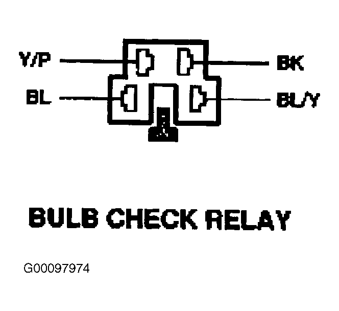 Courtesy of FORD MOTOR CO.
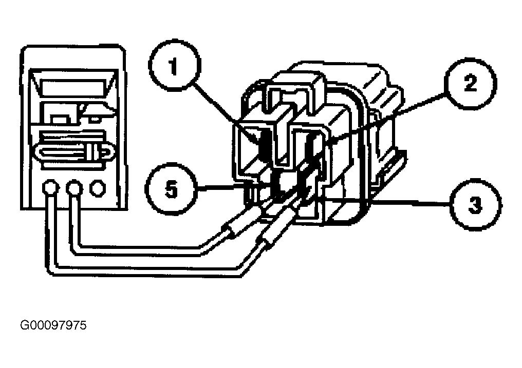 Courtesy of FORD MOTOR CO.