Variable Low Clutch Backing Plate Retaining Ring Measurement
WARNING: This page is about a different variant/trim than selected.
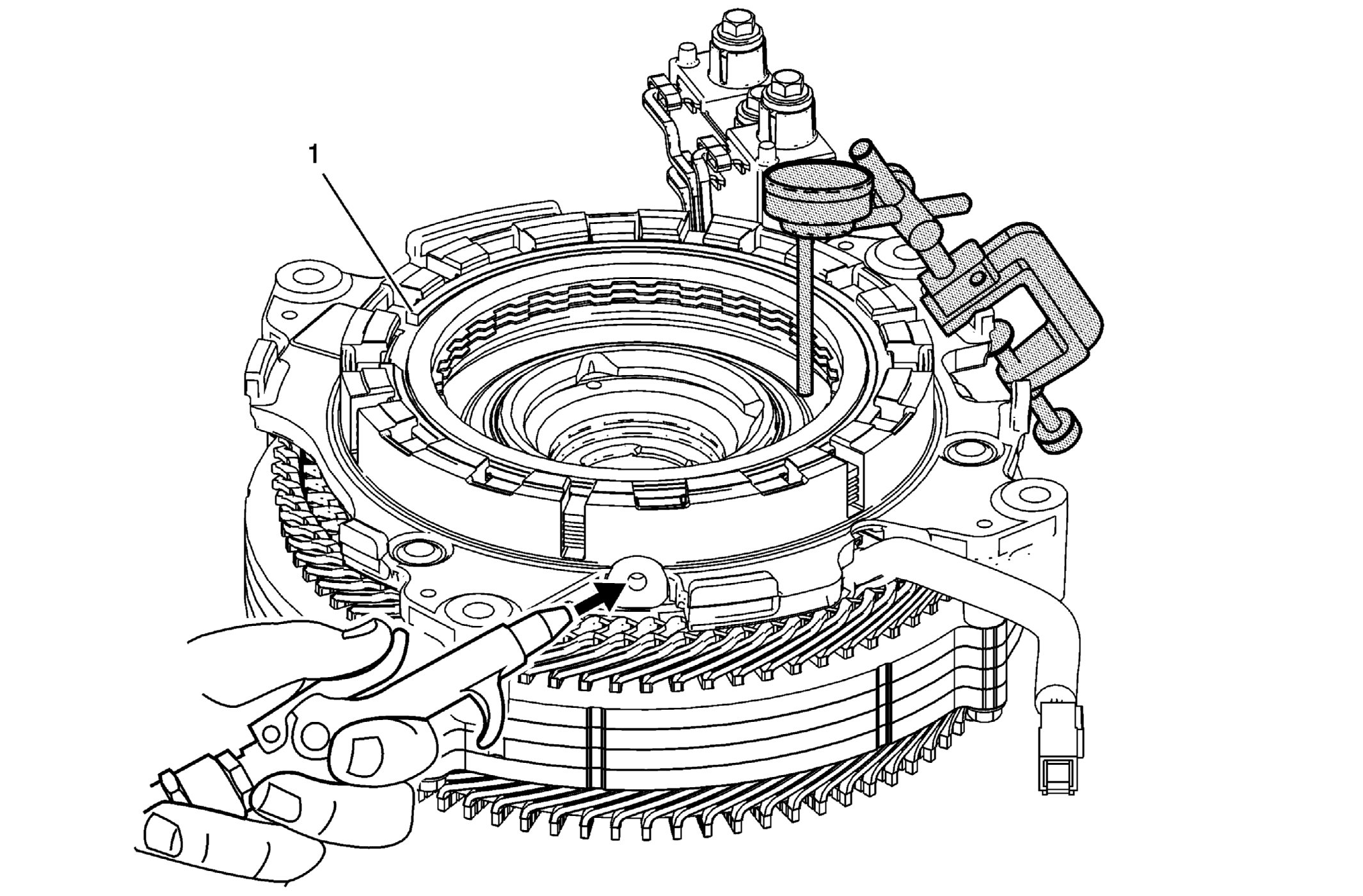 Courtesy of GENERAL MOTORS COMPANY
| Callout |
Component Name |
|
Preliminary Procedure
- Assemble the variable low clutch. Refer to Variable Low Clutch Plate Installation .
- Service the variable low clutch with the variable high clutch installed onto the drive motor rotor. This will prevent contact of the drive motor stator copper end coils with the work surface.
CAUTION:
DO NOT contact or rest the drive motor stator on the copper end coils. Damage to the copper end coils may cause a high voltage short during vehicle operation, resulting in component damage.
|
| 1 |
Variable Low Clutch Backing Plate Retaining Ring Procedure
- Assemble the tools as shown with dial indicator to top of piston.
- Zero out the dial indicator.
- Apply 50 PSI of compressed air.
- Observe the dial indicator measurement. Refer to Clutch Backing Plate Retaining Ring Specifications to determine the correct variable high clutch backing plate retaining ring.
NOTE:
Ensure the plunger of the dial indicator is located on top of the variable low clutch piston.
Special Tools
- GE-7057
Dial Indicator Extension
- GE-8001
Dial Indicator Set
For equivalent regional tools, refer to Special Tools . |