Removal
3UR-FE ENGINE MECHANICAL: CAMSHAFT: REMOVAL
1. REMOVE ENGINE ROOM SIDE COVER LH Removal
2. REMOVE ENGINE ROOM SIDE COVER RH Removal
3. REMOVE UPPER RADIATOR SUPPORT SEAL Removal
4. REMOVE V-BANK COVER SUB-ASSEMBLY Removal
5. DISCHARGE FUEL SYSTEM PRESSURE Removal
6. DISCONNECT CABLE FROM NEGATIVE BATTERY TERMINAL
NOTICE:
- w/ Navigation System:
After the engine switch is turned off, the HDD navigation system requires approximately 6 minutes to record various types of memory and settings. As a result, after turning the engine switch off, wait 6 minutes or more before disconnecting the cable from the negative (-) battery terminal.
- When disconnecting the cable, some systems need to be initialized after the cable is reconnected Repair Instruction - Initialization.
7. REMOVE FRONT FENDER SPLASH SHIELD SUB-ASSEMBLY LH Removal
8. REMOVE FRONT FENDER SPLASH SHIELD SUB-ASSEMBLY RH Removal
9. REMOVE NO. 1 ENGINE UNDER COVER SUB-ASSEMBLY Removal
10. REMOVE NO. 2 ENGINE UNDER COVER Removal
11. REMOVE FRONT FENDER APRON SEAL FRONT LH Removal
12. REMOVE FRONT FENDER APRON SEAL FRONT RH Removal
13. REMOVE RADIATOR GRILLE Removal
14. REMOVE RADIATOR SIDE DEFLECTOR LH Removal
15. REMOVE RADIATOR SIDE DEFLECTOR RH (w/o Air Cooled Transmission Oil Cooler) Removal
16. REMOVE FRONT FENDER MAIN SEAL LH Removal
17. REMOVE FRONT FENDER MAIN SEAL RH Removal
18. REMOVE FRONT WIPER ARM LH Removal
19. REMOVE FRONT WIPER ARM RH Removal
20. REMOVE HOOD TO COWL TOP SEAL Removal
21. REMOVE COWL TOP VENTILATOR LOUVER SUB-ASSEMBLY Removal
22. DRAIN ENGINE OIL Replacement
23. DRAIN ENGINE COOLANT Service and Repair
24. REMOVE AIR CLEANER HOSE ASSEMBLY Removal
25. REMOVE AIR CLEANER ASSEMBLY Removal
26. REMOVE NO. 1 RADIATOR HOSE
27. REMOVE NO. 2 RADIATOR HOSE
28. REMOVE FAN SHROUD Removal
29. REMOVE RADIATOR ASSEMBLY Removal
30. DISCONNECT ENGINE WIRE [1][2]Removal
31. DISCONNECT AIR PUMP HOSE AND WIRE HARNESS [1][2]Removal
32. DISCONNECT NO. 2 WATER BY-PASS PIPE [1][2]Removal
33. DISCONNECT COOLER COMPRESSOR ASSEMBLY [1][2]Removal
34. DISCONNECT NO. 2 FUEL TUBE SUB-ASSEMBLY [1][2]Removal
35. REMOVE OIL FILTER ELEMENT Replacement
36. REMOVE OIL PRESSURE SENDER GAUGE ASSEMBLY Removal
37. REMOVE NO. 2 WATER BY-PASS PIPE SUB-ASSEMBLY (w/ Oil Cooler) [1][2]Removal
38. REMOVE NO. 1 OIL COOLER BRACKET (w/ Oil Cooler) Removal
39. REMOVE OIL FILTER BRACKET (w/ Oil Cooler) Removal
40. REMOVE OIL FILTER BRACKET (w/o Oil Cooler) [1][2]Removal
41. REMOVE INTAKE MANIFOLD Removal
42. DISCONNECT VANE PUMP ASSEMBLY [1][2]Removal
43. REMOVE ENGINE OIL LEVEL DIPSTICK GUIDE Removal
44. DISCONNECT OIL COOLER PIPE ASSEMBLY Removal
45. REMOVE GENERATOR ASSEMBLY Removal
46. REMOVE NO. 1 WATER BY-PASS HOSE [1][2]Removal
47. REMOVE WATER BY-PASS PIPE SUB-ASSEMBLY [1][2]Removal
48. REMOVE FRONT WATER BY-PASS JOINT [1][2]Removal
49. REMOVE NO. 2 ENGINE COVER Removal
50. REMOVE NO. 1 ENGINE COVER Removal
51. REMOVE AIR PIPE SUB-ASSEMBLY [1][2]Removal
52. REMOVE WATER INLET HOUSING [1][2]Removal
53. REMOVE WATER PUMP PULLEY [1][2]Removal
54. REMOVE NO. 1 IDLER PULLEY SUB-ASSEMBLY [1][2]Removal
55. REMOVE FLUID COUPLING BRACKET [1][2]Removal
56. REMOVE V-RIBBED BELT TENSIONER ASSEMBLY [1][2]Removal
57. REMOVE IGNITION COIL ASSEMBLY [1][2]Removal
58. REMOVE CYLINDER HEAD COVER SUB-ASSEMBLY LH [1][2]Removal
59. REMOVE CYLINDER HEAD COVER SUB-ASSEMBLY RH [1][2]Removal
60. REMOVE SPARK PLUG TUBE GASKET [1][2]Disassembly
61. REMOVE CRANKSHAFT PULLEY [1][2]Removal
62. DISCONNECT WIRE HARNESS CLAMP BRACKET [1][2]Removal
63. REMOVE TIMING CHAIN COVER SUB-ASSEMBLY [1][2]Removal
64. REMOVE WATER INLET PIPE [1][2]Removal
65. SET NO. 1 CYLINDER TO TDC/COMPRESSION [1][2]Disassembly
66. REMOVE NO. 1 CHAIN TENSIONER ASSEMBLY LH [1][2]Disassembly
67. REMOVE NO. 1 CHAIN TENSIONER SLIPPER LH [1][2]Disassembly
68. REMOVE NO. 1 CHAIN VIBRATION DAMPER LH [1][2]Disassembly
69. REMOVE NO. 1 CHAIN SUB-ASSEMBLY LH [1][2]Disassembly
70. REMOVE NO. 3 CHAIN TENSIONER ASSEMBLY [1][2]Disassembly
71. REMOVE NO. 1 CHAIN TENSIONER ASSEMBLY RH [1][2]Disassembly
72. REMOVE NO. 1 CHAIN TENSIONER SLIPPER RH [1][2]Disassembly
73. REMOVE NO. 1 CHAIN VIBRATION DAMPER RH [1][2]Disassembly
74. REMOVE NO. 1 CHAIN SUB-ASSEMBLY RH [1][2]Disassembly
75. REMOVE NO. 2 CHAIN TENSIONER ASSEMBLY [1][2]Disassembly
76. REMOVE CRANKSHAFT TIMING GEAR KEY [1][2]Disassembly
77. REMOVE CAMSHAFT BEARING CAP LH
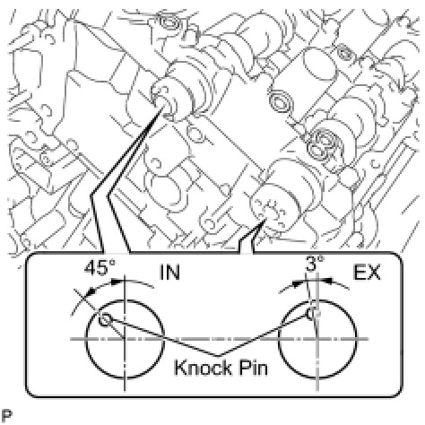
(a) Make sure that the knock pin of the camshaft is positioned as shown in the illustration.
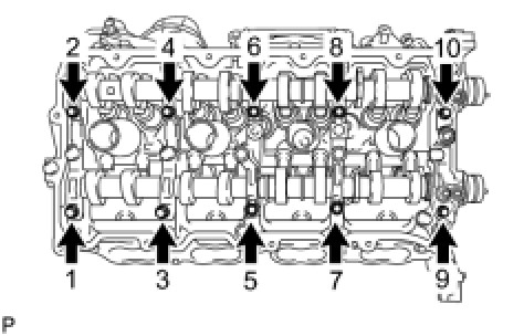
(b) Uniformly loosen and remove the 10 bearing cap bolts in the sequence shown in the illustration.
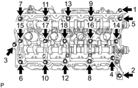
(c) Uniformly loosen and remove the 18 bearing cap bolts in the sequence shown in the illustration.
NOTICE:
Uniformly loosen the bolts while keeping the camshaft level.
(d) Remove the 6 bearing caps.
HINT:
Arrange the removed parts in the correct order.
(e) Remove the No. 3 and No. 4 camshafts.
78. REMOVE CAMSHAFT HOUSING SUB-ASSEMBLY LH
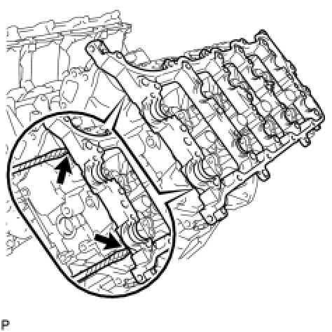
(a) Remove the camshaft housing by prying between the cylinder head and camshaft housing with a screwdriver.
HINT:
Tape the screwdriver tip before use.
NOTICE:
Be careful not to damage the contact surfaces of the cylinder head and camshaft housing.
79. REMOVE CAMSHAFT BEARING CAP RH
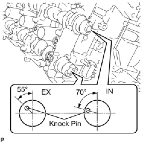
(a) Make sure that the knock pin of the camshaft is positioned as shown in the illustration.
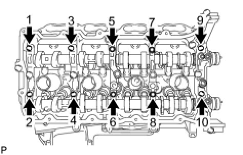
(b) Uniformly loosen and remove the 10 bearing cap bolts in the sequence shown in the illustration.
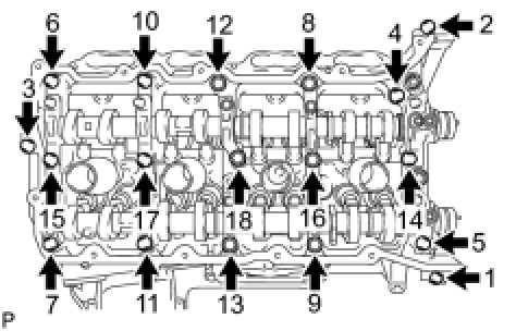
(c) Uniformly loosen and remove the 18 bearing cap bolts in the sequence shown in the illustration.
NOTICE:
Uniformly loosen the bolts while keeping the camshaft level.
(d) Remove the 6 bearing caps.
HINT:
Arrange the removed parts in the correct order.
(e) Remove the No. 1 and No. 2 camshafts.
80. REMOVE CAMSHAFT HOUSING SUB-ASSEMBLY RH
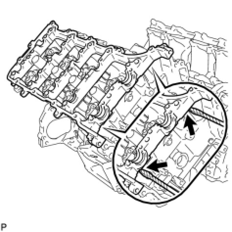
(a) Remove the camshaft housing by prying between the cylinder head and camshaft housing with a screwdriver.
HINT:
Tape the screwdriver tip before use.
NOTICE:
Be careful not to damage the contact surfaces of the cylinder head and camshaft housing.