Test L: Chime Is Inoperative
- If audible warnings diagnostic system check was performed, go to next step. If audible warnings diagnostic system check was not performed, see AUDIBLE WARNINGS DIAGNOSTIC SYSTEM CHECK under DIAGNOSTIC SYSTEM CHECKS.
- Turn ignition on. Turn radio on. Adjust balance and fade to left front speaker. If speaker operates properly, go to next step. If speaker does not operate properly, repair faulty left front speaker.
- Turn ignition off. Connect scan tool to DLC. See Figure. Turn ignition on. Open driver door. Observe DRIVER DOOR AJAR SW. parameter in DOOR MODULE(S) data list. If DRIVER DOOR AJAR SW. parameter displays ON, go to next step. If DRIVER DOOR AJAR SW. parameter does not display ON, see DOOR AJAR MESSAGE INOPERATIVE .
- Turn headlights on. Observe HEAD LAMP SWITCH parameter in DASH INTEGRATION MODULE (DIM) INPUTS data list on scan tool. If HEAD LAMPS parameter displays ON, go to next step. If HEAD LAMPS parameter does not display ON, see HEADLIGHTS INOPERATIVE - LOW BEAMS under SYSTEM TESTS in HEADLIGHT SYSTEMS & DAYTIME RUNNING LIGHTS article.
- Turn ignition on. Observe KEY IN IGNITION parameter in INSTRUMENT PANEL MODULE (IPM) NON HVAC data list. If KEY IN IGNITION parameter does not display YES, go to next step. If KEY IN IGNITION parameter displays YES, go to step 7.
- Turn ignition off. Disconnect ignition switch harness connector. Connect a fused jumper wire (3-amp) between ground and (key in ignition signal circuit) ignition switch harness connector terminal No. 2 (Light Green wire). See Figure. Observe KEY IN IGNITION parameter. If KEY IN IGNITION parameter displays YES, go to step 9. If KEY IN IGNITION parameter does not display YES, go to step 8.
- Turn ignition OFF. Disconnect radio amplifier. Insert key in ignition. Open driver's door. Use Digital Multimeter (DMM) measure AC voltage between radio amplifier harness connector C3, terminals B8 (Dark Blue/White wire) and B9 (Purple/White wire) if not equipped with navigation or terminals B12 (Dark Blue/White wire) and A12 (Purple/White wire) if equipped with navigation. See Figure or Figure
. If 0.6-0.7 volts AC exist, go to step 14. If 0.6-0.7 volts AC does not exist, go to step 10.
- Check for short to ground in Light Green wire between ignition switch harness connector terminal No. 2 and IPM harness connector C1 terminal B9. If no problem was found, go to step 13. If a problem was found and corrected, go to step 20.
- Check for an open in Black wire between ignition switch harness connector terminal No. 3 and ground (located at right front passenger's door jamb). See Figure. If no problem was found, go to step 12. If a problem was found and corrected, go to step 20.
- Check for an open, short to ground or short to voltage in Dark Blue/White wire between radio amplifier harness connector C3, terminal B8 if not equipped with navigation or terminal B12 if equipped with navigation and radio harness connector terminal F13. See Figure or Figure and Fig 1
. If no problem was found, go to next step. If a problem was found and corrected, go to step 20.
- Check for an open, short to ground or short to voltage in Purple/White wire between radio amplifier harness connector C3, terminal B9 if not equipped with navigation or terminal A12 if equipped with navigation and radio harness connector terminal F12. See Figure or Figure and Fig 1
. If no problem was found, go to step 15. If a problem was found and corrected, go to step 20.
- Check for faulty connections at ignition switch. If no problem was found, go to step 16. If a problem was found and corrected, go to step 20.
- Check for faulty connections at IPM. If no problem was found, go to step 17. If a problem was found and corrected, go to step 20.
- Check for faulty connections at radio amplifier. If no problem was found, go to step 18. If a problem was found and corrected, go to step 20.
- Check for faulty connections at radio. If no problem was found, go to step 19. If a problem was found and corrected, go to step 20.
- Replace ignition switch. See IGNITION & KEY ALARM SWITCH ASSEMBLY under REMOVAL & INSTALLATION in STEERING COLUMN SWITCHES - DEVILLE article. After replacement go to step 20.
- Replace PCM. See POWERTRAIN CONTROL MODULE under REMOVAL & INSTALLATION in BODY CONTROL MODULES - DEVILLE article. After repairs, go to step 20.
- Replace radio amplifier. See RADIO AMPLIFIER under REMOVAL & INSTALLATION in BODY CONTROL MODULES - DEVILLE article. After replacement go to step 20.
- Replace radio. See RADIO under REMOVAL & INSTALLATION in BODY CONTROL MODULES - DEVILLE article. After replacement go to next step.
- After repairs, recheck operation of chime. If chime operates properly, repair is complete. If chime does not operate properly, return to step 2.
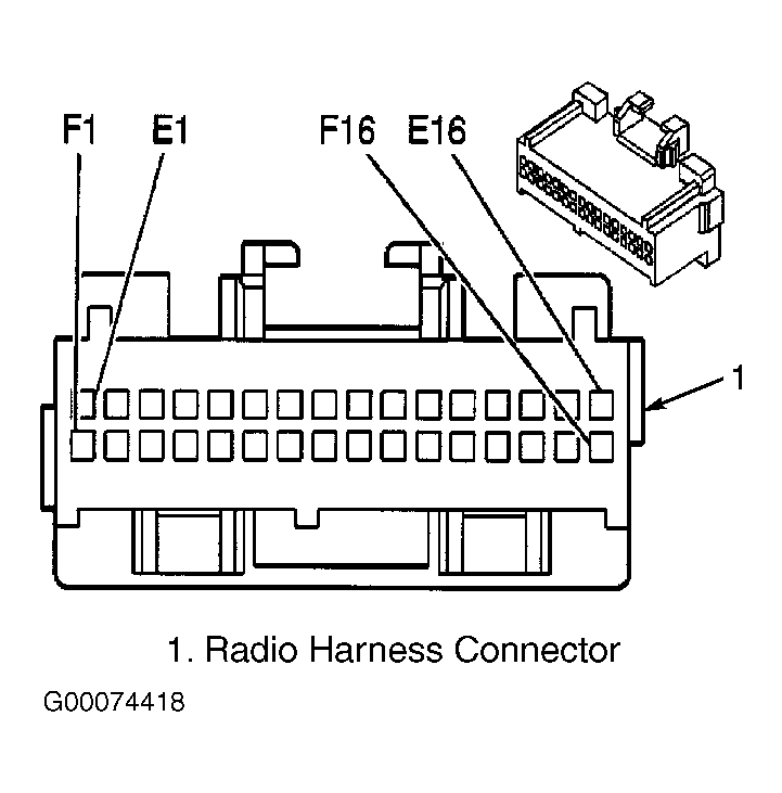 Courtesy of GENERAL MOTORS CORP.