Master cylinder, removing and installing
WARNING: This page is about a different car, the 2004 Audi A4, 2003 Audi A4, and 2002 Audi A4. However, it is still accessible from the selected car via links, so may be relevant.
Special tools, testers and other items required
- 3094 Hose clamp
- VAG 1922 Pliers
Removing
- Pull off gasket on plenum chamber in direction of arrow.
- Remove cover -1- on top of plenum chamber.
- First check if a coded radio is installed. In this case obtain anti-theft code.
See Caution for disconnecting Telematics battery. Refer to Clutch mechanism components (on chassis)
- Disconnect battery Ground strap with ignition switched off.
- Pry off two covers -3- with a screwdriver.
- Remove nuts -4- and two wiper arms -2-.
- Pull off clips -1- and remove cowl panel grille -5-.
Remove electronics box in plenum chamber as follows:
- Remove bolts (arrows) and take off cover lid.
- Carefully pry off mount bar with screwdriver (arrow).
- Loosen connector locks (arrows) and unplug connectors -1- and -2- from engine control module.
- Remove connectors -2- from connector strip.
- Disconnect electrical connection -1-.
- Release locks (arrows) and pull auxiliary relay carrier in electronics box upward and off.
- Pull engine wiring harness together with grommet out of recess in electronics box.
- Remove nuts (arrows) and lift out electronics box -1-.
NOTE:
- During the following steps make sure that brake fluid does not escape into plenum chamber or onto transmission below. If it does, clean affected area thoroughly.
- When working in footwell, cover carpet with cloths to protect it from brake fluid spillage.
- Disconnect supply hose -A- to brake fluid reservoir with special tool 3094, disconnect from master cylinder and seal with plug.
- On bulkhead remove grommet above connecting tube for supply hose.
- Pry out securing clip -C- with screwdriver and then pull tube -B- out slightly.
- Remove bolt for brake fluid reservoir -1- and unplug connector for monitoring fluid level by pulling downward.
NOTE:
Do not remove brake fluid reservoir.
NOTE:
- Brake fluid reservoir not shown for purpose of clearer illustration.
- To remove the top TORX bolt; swivel brake fluid reservoir sideways slightly.
- Remove two TORX bolts (arrows).
- Remove vacuum tube to brake booster -1-.
- Remove driver's storage compartment.
Refer to
- 68 - INTERIOR EQUIPMENT
- 68 - INTERIOR EQUIPMENT for Cabriolet
- Separate brake pedal from brake booster.
Refer to 47 - BRAKES - HYDRAULIC COMPONENTS
Fig 15: Locating Steering Column At Steering Gear And Disconnecting Connector On Clutch Pedal Switch, Brake Pedal Switch And On Accelerator Pedal Module
- Separate steering column from steering box (arrow A).
Refer to 48 - STEERING
- Disconnect connectors from clutch pedal switch -1-, brake pedal switch -2- and accelerator pedal module -3-.
- Remove bolt for mounting bracket (arrow B) and remove pedal cluster assembly.
Release master cylinder operating rod from clutch pedal as follows:
- Remove over-center spring. Refer to Over-center spring, removing and installing .
NOTE:
 Courtesy of VOLKSWAGEN UNITED STATES, INC.
- When releasing make sure clutch pedal does not bounce against clutch pedal switch mount (arrow). Otherwise the mount might break.
- In order to assure sufficiently secure fitting of clutch pedal switch. Refer to Pedal cluster, assembly overview Item 6- as well as Clutch pedal starter interlock switch -F194-. Refer to Pedal cluster, assembly overview Item 14- in pedal cluster, these switches must not be installed more than once.
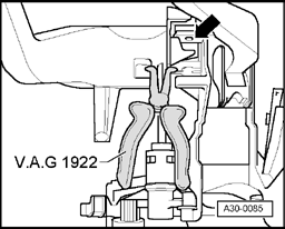
- Insert pliers VAG 1922 into recesses in clutch pedal, compress mount (arrows) and separate clutch pedal from master cylinder.
- Remove securing clip -1- and clutch pedal -2-.
- Remove bolts -3- and master cylinder -4-.
Installing
Install in reverse order, paying attention to the following:
- Insert master cylinder and tighten bolts -3- to 20 Nm.
Fig 19: Pushing Clutch Pedal To Lock Into Place, While Making Sure Mount Is Properly Secured In Clutch Pedal
- Insert mount -1- in clutch pedal.
- Push clutch pedal in direction of arrow to lock into place, while making sure mount -1- is properly secured in clutch pedal.
- Installing over-center spring. Refer to Over-center spring, removing and installing .
For the next step a second technician is required.
- Insert pedal cluster assembly and tighten bolt -1- hand-tight. Simultaneously, second technician feeds tube from plenum chamber side into master cylinder.
- Tighten brake booster bolts (arrows) to 25 Nm.
- Push in securing clip -C- as far as it will go.
- Insert tube -B- in master cylinder until it clicks into position.
- Install grommet -D- over connecting tube/supply hose -A- and into bulkhead.
- Push on supply hose -A- to brake fluid reservoir as far as it will go.
- Remove special tool 3094.
- Screw in brake fluid reservoir bolt.
- Tighten hex socket-head bolt (arrow B) which secures pedal cluster to instrument panel carrier to 25 Nm.
- Attach connectors -1-, -2- and -3-.
- Connect brake pedal to brake booster.
Refer to 47 - BRAKES - HYDRAULIC COMPONENTS
- Attach steering column to steering box (arrow A).
Refer to 48 - STEERING
- Install driver's storage compartment:
Refer to
- 68 - INTERIOR EQUIPMENT
- 68 - INTERIOR EQUIPMENT for Cabriolet
- Bleed clutch system. Refer to Clutch system, bleeding .
- Insert electronics box and tighten nuts (arrows) to 4 Nm.
- Route engine wiring harness and attach connection in connector station.
- Install engine control module plus auxiliary relay carrier and auxiliary fuse holder, if installed.
Refer to 97 WIRING r.
- Push on cover lid by hand and tighten bolts diagonally - 4 Nm.
See Caution for connecting Telematics battery. Refer to Clutch mechanism components (on chassis)
NOTE:
If the battery is reconnected remember to check and activate vehicle equipment (radio, clock, convenience electronics etc.).
Refer to
- 01 - MAINTENANCE
- 01 - MAINTENANCE for Cabriolet