Special tools:
9988695
Ignition off. Disconnect battery negative lead
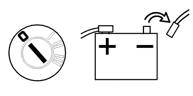 Courtesy of VOLVO CARS OF NORTH AMERICA.
Check that the customer has left the radio code.
WARNING:
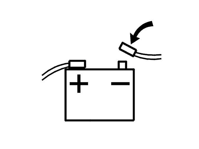
Before assembling the steering wheel the ignition should be in position II. Then the battery negative should be reconnected. See Conclusion . Ensure that nobody is in the car when the battery is being connected.
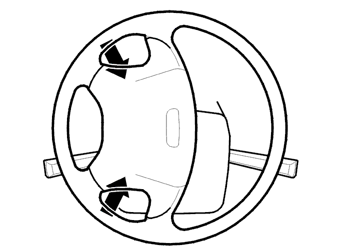
Removing steering wheel screws
 Courtesy of VOLVO CARS OF NORTH AMERICA.
Leave the screws on the reverse of the steering wheel in their countersunk holes.
2 Torx 30 screws.
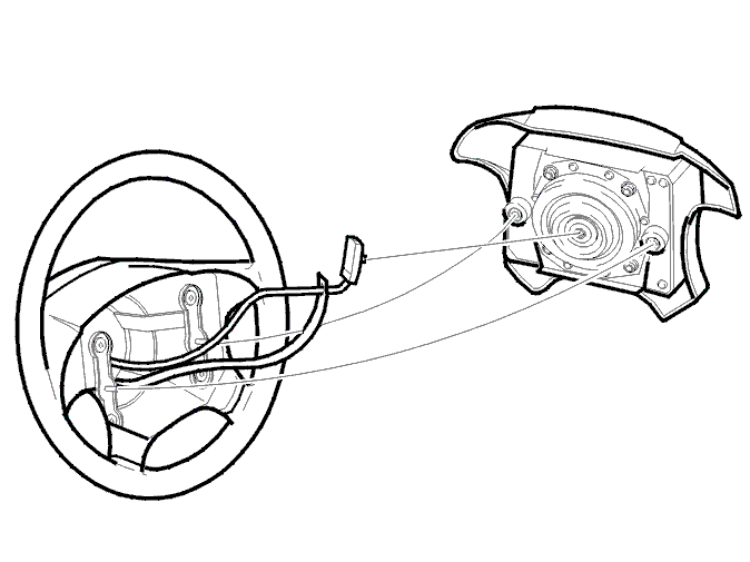
Removing steering wheel module
 Courtesy of VOLVO CARS OF NORTH AMERICA.
WARNING:
The battery must not be connected when the SRS ignition cable connector is removed or installed.
WARNING:
Under no circumstances use an ohmmeter or other live measuring instrument to take readings on a disconnected, non-deployed airbag module. This could deploy the airbag.
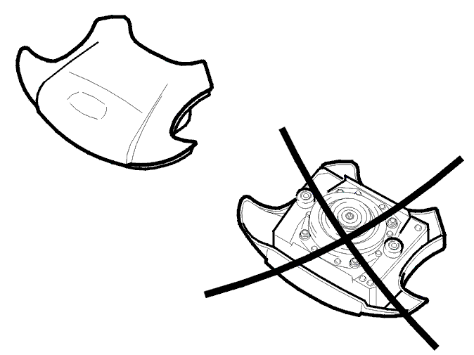
Placing the Steering Wheel Module
 Courtesy of VOLVO CARS OF NORTH AMERICA.
CAUTION:
If a non-deployed steering wheel module is removed temporarily, it should be placed with the metal side (rear) downwards in a protected place.
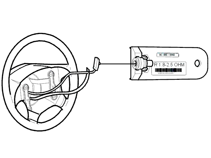
Connecting special tool
 Courtesy of VOLVO CARS OF NORTH AMERICA.
Connect special tool
9988695
If the ignition is switched on when neither the steering wheel module nor special tool are connected, a diagnostic trouble code (DTC) will be stored indicating an open-circuit. Any diagnostic trouble code (DTC) must be erased.
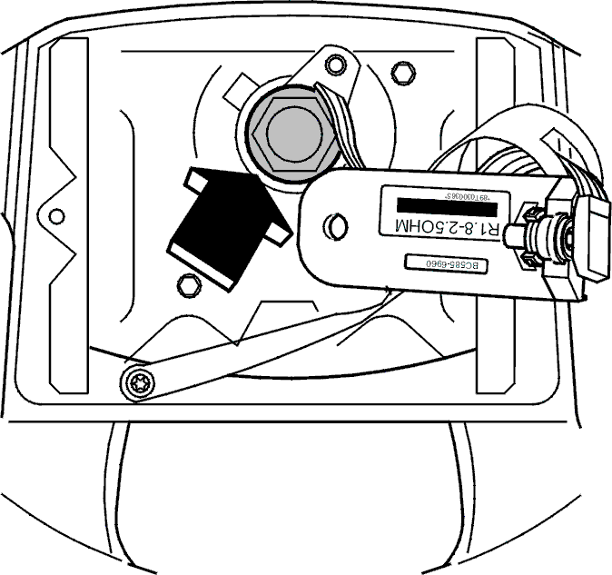
Slacken off center screw
 Courtesy of VOLVO CARS OF NORTH AMERICA.
Slacken off the screw but leave it in place. The screw should be loose enough to unscrew by hand.
Reconnect the battery negative lead
 Courtesy of VOLVO CARS OF NORTH AMERICA.
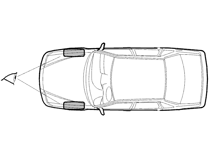
Align front wheels
 Courtesy of VOLVO CARS OF NORTH AMERICA.
- Drive the car straight forwards or backwards on a level surface so that the wheels point straight ahead.
CAUTION:
It is always important to point the wheels straight ahead when carrying out work that requires the removal of the steering wheel and/or contact reel.
WARNING:
Do not drive the car further than necessary to align the front wheels. The steering wheel is not properly tightened and the steering wheel module has been removed.
Disconnect the Battery Negative Lead
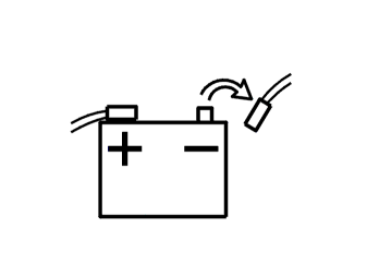 Courtesy of VOLVO CARS OF NORTH AMERICA.
Remove special tool
Courtesy of VOLVO CARS OF NORTH AMERICA.
Remove special tool
9988695
HINT: If the ignition is switched on when neither the steering wheel module nor special tool are connected, a diagnostic trouble code (DTC) will be stored indicating an open-circuit. Any diagnostic trouble code (DTC) must be erased.
Secure the contact reel
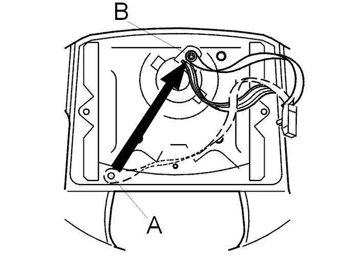 Courtesy of VOLVO CARS OF NORTH AMERICA.
Remove screw from parking position (A) and secure the contact reel in lock position (B). Do not detach the screw from the plastic strip.
CAUTION:
The steering wheel must never be turned while the contact reel is locked. The contact reel pin will shear off.
Remove the steering wheel center screw
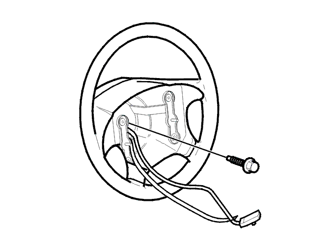 Courtesy of VOLVO CARS OF NORTH AMERICA.
Remove steering wheel, steering wheel covers and switches
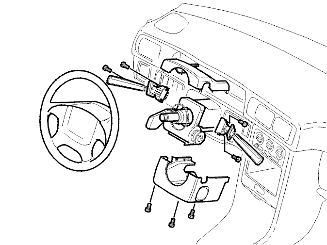 Courtesy of VOLVO CARS OF NORTH AMERICA.
CAUTION:
The steering wheel must never be turned while the contact reel is locked. The contact reel pin will shear off.
3 Torx 20 screws in the steering wheel cover.
2 Torx 20 screws in the switches.
To remove and install contact reel, see Replacing SRS Contact Reel
.