- INSTALL OIL COOLER SPACER
 Courtesy of © TOYOTA, LICENSE AGREEMENT TMS1002 Courtesy of © TOYOTA, LICENSE AGREEMENT TMS1002
|
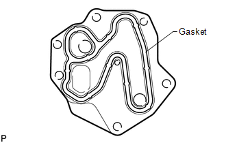
Apply a light coat of engine oil to a new gasket.
- Install the gasket to the oil cooler spacer.
 Courtesy of © TOYOTA, LICENSE AGREEMENT TMS1002 Courtesy of © TOYOTA, LICENSE AGREEMENT TMS1002
|
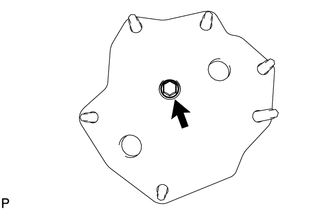
Install the oil cooler spacer to the oil filter bracket with the bolt.
Torque: 10 N*m (102 kgf*cm, 7 ft.*lbf)
- INSTALL OIL COOLER ASSEMBLY
 Courtesy of © TOYOTA, LICENSE AGREEMENT TMS1002 Courtesy of © TOYOTA, LICENSE AGREEMENT TMS1002
|
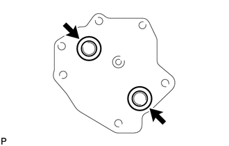
Apply a light coat of engine oil to 2 new O-rings.
- Install the 2 O-rings to the oil cooler.
 Courtesy of © TOYOTA, LICENSE AGREEMENT TMS1002 Courtesy of © TOYOTA, LICENSE AGREEMENT TMS1002
|
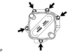
Install the oil cooler with the 5 nuts.
Torque: 21 N*m (214 kgf*cm, 15 ft.*lbf)
- INSTALL OIL FILTER BRACKET
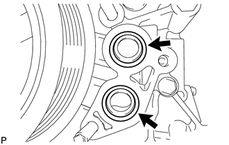 Courtesy of © TOYOTA, LICENSE AGREEMENT TMS1002 Courtesy of © TOYOTA, LICENSE AGREEMENT TMS1002
|
Apply a light coat of engine oil to 2 new O-rings.
- Install the 2 O-rings to the timing chain cover.
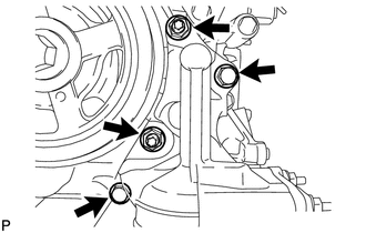 Courtesy of © TOYOTA, LICENSE AGREEMENT TMS1002 Courtesy of © TOYOTA, LICENSE AGREEMENT TMS1002
|
Install the oil filter bracket with the 2 nuts and 2 bolts.
Torque: 35 N*m (357 kgf*cm, 26 ft.*lbf)
- INSTALL NO. 1 OIL COOLER BRACKET
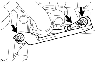 Courtesy of © TOYOTA, LICENSE AGREEMENT TMS1002 Courtesy of © TOYOTA, LICENSE AGREEMENT TMS1002
|
Connect the ground wire to the cylinder block.
- Install the oil cooler bracket with the 2 nuts.
Torque: 21 N*m (214 kgf*cm, 15 ft.*lbf)
- INSTALL NO. 2 WATER BY-PASS PIPE SUBASSEMBLY
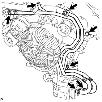 Courtesy of © TOYOTA, LICENSE AGREEMENT TMS1002 Courtesy of © TOYOTA, LICENSE AGREEMENT TMS1002
|
Connect the 4 hoses.
- Install the water by-pass hose with the 3 bolts.
Torque: 10 N*m (102 kgf*cm, 7 ft.*lbf)
- CONNECT COOLER COMPRESSOR ASSEMBLY
See step 31
- INSTALL OIL PRESSURE SENDER GAUGE ASSEMBLY
See step 1
- INSTALL OIL FILTER ELEMENT
See step 5
- INSTALL FAN & GENERATOR V BELT
Refer to PROCEDURE - Step 1
- INSTALL V-BANK COVER SUBASSEMBLY
Refer to PROCEDURE - Step 46
- ADD ENGINE OIL
See step 6
- ADD ENGINE COOLANT
Refer to PROCEDURE - Step 5
- CONNECT CABLE TO NEGATIVE BATTERY TERMINAL
- INSPECT FOR OIL LEAK
See step 7
- INSPECT ENGINE OIL LEVEL
Refer to PROCEDURE - Step 2
- INSPECT FOR COOLANT LEAK
Refer to PROCEDURE - Step 1
- INSTALL NO. 1 ENGINE UNDER COVER SUBASSEMBLY
Refer to PROCEDURE - Step 49
- INSTALL FRONT FENDER SPLASH SHIELD SUBASSEMBLY LH
Refer to PROCEDURE - Step 14
- INSTALL FRONT FENDER SPLASH SHIELD SUBASSEMBLY RH
Refer to PROCEDURE - Step 15