Diagnostic Procedure
- Turn ignition switch to ACC or On position. Wait at least 20 seconds. Clear DTCs. See CLEARING CODES under DIAGNOSIS & TESTING. Turn ignition switch to LOCK position. Wait at least 20 seconds. Turn ignition switch to ACC or ON position. Wait at least 20 seconds. Retrieve DTCs. See RETRIEVING CODES under DIAGNOSIS & TESTING. If DTC 32 is not displayed, go to step 8). If DTC 32 is displayed, go to next step.
- Access right-side air bag sensor assembly. See SIDE AIR BAG SENSOR ASSEMBLY under REMOVAL & INSTALLATION . Ensure right-side air bag sensor assembly harness connector is properly connected and secure. Reconnect if necessary. Go to next step.
- Disable air bag system. See DISABLING SYSTEM under DISABLING & ACTIVATING AIR BAG SYSTEM.
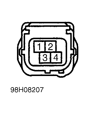
- Disconnect right-side air bag sensor assembly connector. Connect jumper wire between right-side air bag sensor assembly harness connector terminals No. 2 (circuit SSR+, Blue/Yellow wire) and No. 4 (circuit ESR, Gray wire). See Fig 1. Measure resistance between air bag sensor assembly connector C18, terminals No. 9 (circuit SSR+, Blue/Yellow wire) and 12 (circuit ESR, Gray wire). See Figure. If resistance is less than one ohm, go to next step. If resistance is more than one ohm, repair or replace harness or connector between right-side air bag sensor assembly and air bag sensor assembly.
- Connect jumper wire between right-side air bag sensor assembly harness connector terminals No. 1 (circuit VUPR, Pink wire) and No. 3 (circuit FSR, Light Green wire). See Fig 1. Measure resistance between air bag sensor assembly connector C18, terminals No. 7 (circuit VUPR, Pink wire) and 10 (circuit FSR, Light Green wire). See Figure. If resistance is less than one ohm, go to next step. If resistance is more than one ohm, repair or replace harness or connector between right-side air bag sensor assembly and air bag sensor assembly.
 Courtesy of © TOYOTA, LICENSE AGREEMENT TMS1002
- Measure resistance between ground and air bag sensor assembly harness connector C18, terminals No. 7 (circuit VUPR, Pink wire), No. 9 (circuit SSR+, Blue/Yellow wire) and No. 10 (circuit FSR, Light Green wire) individually. See Figure. If resistance is more than one megohm, go to next step. If resistance is less than one megohm, repair or replace harness or connector between right-side air bag sensor assembly and air bag sensor assembly. See WIRING DIAGRAMS .
- Connect negative battery cable. Turn ignition switch to ACC or ON position. Measure voltage between ground and air bag sensor assembly harness connector C18, terminals No. 7 (circuit VUPR, Pink wire), No. 9 (circuit SSR+, Blue/Yellow wire), No. 10 (circuit FSR, Light Green wire) and No. 12 (circuit ERS, Gray wire) individually. See Figure. If zero volt is present, turn ignition switch to LOCK position, disconnect negative battery cable and go to next step. If more than zero volt is present, repair or replace harness or connector between right-side air bag sensor assembly and air bag sensor assembly. See WIRING DIAGRAMS .
- Ensure negative battery cable is disconnected. Reconnect all system components. Connect negative battery cable. Wait at least 2 seconds. Turn ignition switch to ACC or ON position. Wait at least 20 seconds. Clear DTCs. See CLEARING CODES under DIAGNOSIS & TESTING. Turn ignition switch to LOCK position. Wait at least 20 seconds. Turn ignition switch to ACC or ON position. Wait at least 20 seconds. Retrieve DTCs. See RETRIEVING CODES under DIAGNOSIS & TESTING. If DTC 32 is not displayed, system is functioning properly at this time. Check for intermittent fault. See AIR BAG WARNING LIGHT INTERMITTENT . If DTC 32 is displayed, replace right-side air bag sensor assembly.