Piston & Rod Assembly
- Note direction of connecting rod installation on piston before removing. Check rods for bend and twist. Replace rods if bend or twist exceeds specification. See CONNECTING RODS table under ENGINE SPECIFICATIONS.
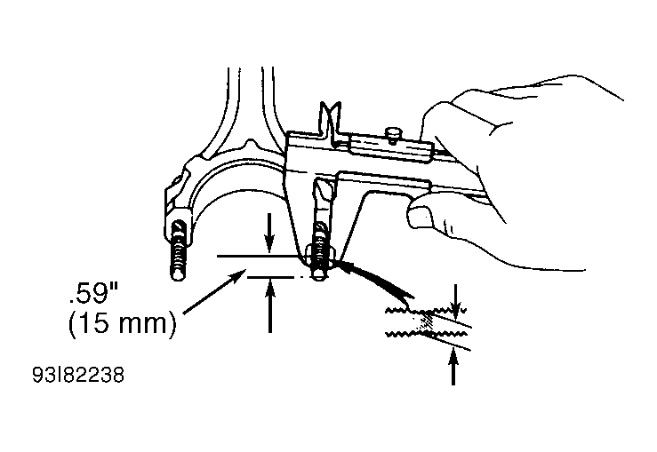
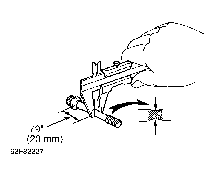
- Measure connecting rod bolts for stretch. On 1.6L, measure rod bolt .59" (15 mm) from rod. See Fig 1. Minimum diameter is .3386" (8.60 mm). On 1.8L, measure rod bolt .787" (20 mm) from head of bolt. See Fig 1. Minimum diameter is .276" (7 mm). On all engines replace rod bolt and nut if less than minimum diameter.
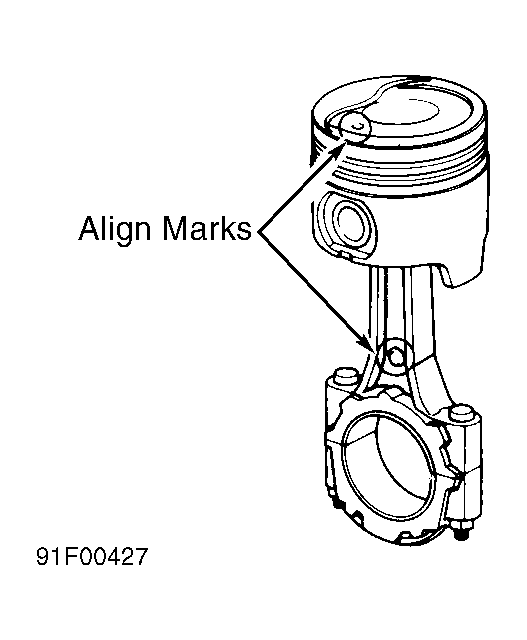
- Note mark at center of connecting rod, which must be aligned with front mark on top of piston. See Fig 1 & Fig 2
. Install connecting rod in original direction. Install piston with front mark on piston top toward timing belt end of engine.
 Courtesy of © TOYOTA, LICENSE AGREEMENT TMS1002
 Courtesy of © TOYOTA, LICENSE AGREEMENT TMS1002
 Courtesy of © TOYOTA, LICENSE AGREEMENT TMS1002
NOTE:
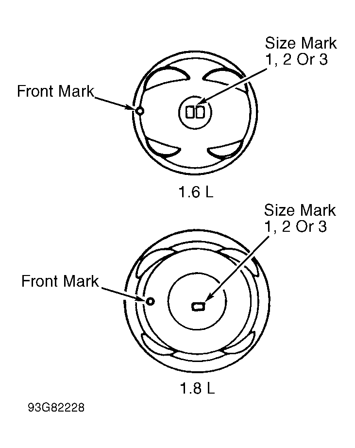
Three different standard sizes of piston and cylinder bore are used. Piston and cylinder bore sizes are identified by a numerical size mark, "1", "2" or "3". Piston size is stamped on piston top and cylinder bore size is stamped on cylinder block deck surface. See Fig 4 and Figure
.
 Courtesy of © TOYOTA, LICENSE AGREEMENT TMS1002