| 1 |
CHECK FOR INTAKE AIR LEAK AND PCV HOSE
- Start engine and run it at idle speed.
- Listen for the sound of the intake air leak.
- Check PCV hose connection.
OK or NG |
GO TO 2. |
Discover air leak location and repair. |
| 2 |
CHECK FOR EXHAUST SYSTEM CLOGGING
Stop engine and visually check exhaust tube, three way catalyst and muffler for dents.
OK or NG |
GO TO 3. |
GO TO 4. |
| 3 |
PERFORM POWER BALANCE TEST
With SDT
- Perform "POWER BALANCE" in "Active test" mode.
- Is there any cylinder which does not produce a momentary engine speed drop?
Yes or No |
GO TO 4. |
GO TO 10. |
| 4 |
CHECK FUNCTION OF FUEL INJECTOR-I
Stop engine.
- Disconnect harness connector F44 (3), F201 (1)
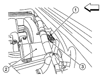 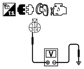  Courtesy of SUZUKI OF AMERICA CORP.SUZUKI OF AMERICA CORP.SUZUKI OF AMERICA CORP. Courtesy of SUZUKI OF AMERICA CORP.SUZUKI OF AMERICA CORP.SUZUKI OF AMERICA CORP.
2: Vacuum tank
<=: Front
- 2. Turn ignition switch ON.
- 3. Check voltage between harness connector F44 terminal 3 and ground with SDT or tester.
Courtesy of SUZUKI OF AMERICA CORP.SUZUKI OF AMERICA CORP.SUZUKI OF AMERICA CORP.
Voltage: Battery voltage
- 4. Turn ignition switch OFF.
- 5. Disconnect ECM harness connector.
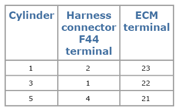
- 6. Check harness continuity between harness connector F44 and ECM as follows.
Refer to WIRING DIAGRAM
.
Courtesy of SUZUKI OF AMERICA CORP.SUZUKI OF AMERICA CORP.SUZUKI OF AMERICA CORP.
Continuity should exist.
- 7. Also check harness for short to ground and short to power.
OK or NG |
GO TO 5. |
Perform trouble diagnosis for FUEL INJECTOR, refer to
[FUEL INJECTOR CIRCUIT CHECK
]. |
| 5 |
CHECK FUNCTION OF FUEL INJECTOR-II
Provide battery voltage between harness connector F201 as follows and then interrupt it. Listen to each fuel injector operating sound.
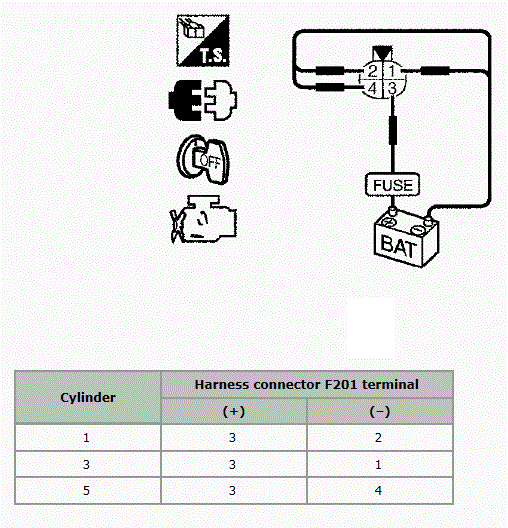 Courtesy of SUZUKI OF AMERICA CORP. Courtesy of SUZUKI OF AMERICA CORP.
Operating sound should exist.
OK or NG |
GO TO 6. |
Perform trouble diagnosis for FUEL INJECTOR, refer to
[FUEL INJECTOR CIRCUIT CHECK
]. |
| 6 |
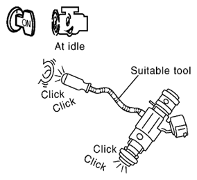
CHECK FUNCTION OF FUEL INJECTOR-III
- Reconnect all harness connector disconnected.
- Start engine.
- Listen to fuel injectors No. 2, No. 4, No. 6 operating sound.
 Courtesy of SUZUKI OF AMERICA CORP. Courtesy of SUZUKI OF AMERICA CORP.
Clicking noise should exist.
OK or NG |
GO TO 7. |
Perform trouble diagnosis for FUEL INJECTOR, refer to
[FUEL INJECTOR CIRCUIT CHECK
]. |
| 7 |
CHECK FUNCTION OF IGNITION COIL-I
CAUTION:
Perform the following procedure in a place with no combustible objects and good ventilation.
- Turn ignition switch OFF.
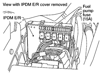
- Remove fuel pump fuse (No. 48) in IPDM E/R to release fuel pressure.
  Courtesy of SUZUKI OF AMERICA CORP.SUZUKI OF AMERICA CORP. Courtesy of SUZUKI OF AMERICA CORP.SUZUKI OF AMERICA CORP.
NOTE:
Do not use SDT to release fuel pressure, or fuel pressure applies again during the following procedure.
- 3. Start engine.
- 4. After engine stalls, crank it two or three times to release all fuel pressure.
- 5. Turn ignition switch OFF.
- 6. Remove all ignition coil harness connectors to avoid the electrical discharge from the ignition coils.
- 7. Remove ignition coil and spark plug of the cylinder to be checked.
- 8. Crank engine for five seconds or more to remove combustion gas in the cylinder.
- 9. Connect spark plug and harness connector to ignition coil.
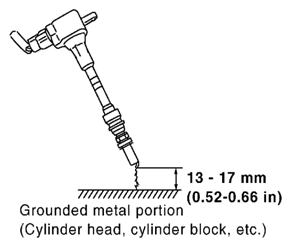
- 10. Fix ignition coil using a rope etc. with gap of 13 - 17 mm (0.52 - 0.66 in) between the edge of the spark plug and grounded metal portion as shown in the figure.
Courtesy of SUZUKI OF AMERICA CORP.SUZUKI OF AMERICA CORP.
- 11. Crank engine for about three seconds, and check whether spark is generated between the spark plug and the grounded metal portion.
Spark should be generated.
CAUTION:
- Never place to the spark plug and the ignition coil within 50cm (19.7 in) each other. Be careful not to get an electrical shock while checking, because the electrical discharge voltage becomes 20 kV or more.
- It might cause to damage the ignition coil if the gap of more than 17 mm (0.66 in) is made.
NOTE:
When the gap is less than 13 mm (0.52 in), the spark might be generated even if the coil is malfunctioning.
OK or NG |
GO TO 11. |
GO TO 8. |
| 8 |
CHECK FUNCTION OF IGNITION COIL-II
- Turn ignition switch OFF.
- Disconnect spark plug and connect a known-good spark plug.
- Crank engine for about three seconds, and recheck whether spark is generated between the spark plug and the grounded metal portion.
Spark should be generated.
OK or NG |
GO TO 9. |
Check ignition coil, power transistor and their circuits. Refer to
[IGNITION SIGNAL CIRCUIT CHECK
]. |
| 9 |
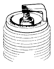
CHECK SPARK PLUG
Check the initial spark plug for fouling, etc.
 Courtesy of SUZUKI OF AMERICA CORP. Courtesy of SUZUKI OF AMERICA CORP.
OK or NG |
Replace spark plug(s) with standard type one(s). For spark plug type, refer to
[SPARK PLUG: REMOVAL AND INSTALLATION
] |
- Repair or clean spark plug.
- GO TO 10.
|
| 10 |
CHECK FUNCTION OF IGNITION COIL-III
- Reconnect the initial spark plugs.
- Crank engine for about three seconds, and recheck whether spark is generated between the spark plug and the grounded portion.
Spark should be generated.
OK or NG |
INSPECTION END |
Replace spark plug(s) with standard type one(s). For spark plug type, refer to
[SPARK PLUG: REMOVAL AND INSTALLATION
] |
| 11 |
CHECK COMPRESSION PRESSURE
Check compression pressure. Refer to
[COMPRESSION PRESSURE
]
OK or NG |
GO TO 12. |
Check pistons, piston rings, valves, valve seats and cylinder head gaskets. |
| 12 |
CHECK FUEL PRESSURE
- Install all removed parts.
- Release fuel pressure to zero. Refer to
[FUEL PRESSURE CHECK: VQ40DE
]
- Install fuel pressure gauge and check fuel pressure. Refer to
[FUEL PRESSURE CHECK: VQ40DE
]
At idle: Approx. 350 kPa (3.57 kg/cm 2
, 51 psi)
OK or NG |
GO TO 14. |
GO TO 13. |
| 13 |
DETECT MALFUNCTIONING PART
Check the following.
|
Repair or replace. |
|
| 14 |
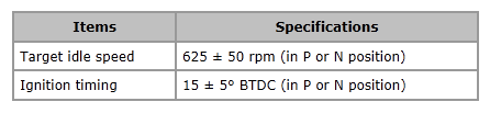
CHECK IGNITION TIMING
Check the following items. Refer to
[BASIC INSPECTION
].
 Courtesy of SUZUKI OF AMERICA CORP. Courtesy of SUZUKI OF AMERICA CORP.
OK or NG |
GO TO 15. |
Follow the
[BASIC INSPECTION
]. |
| 15 |
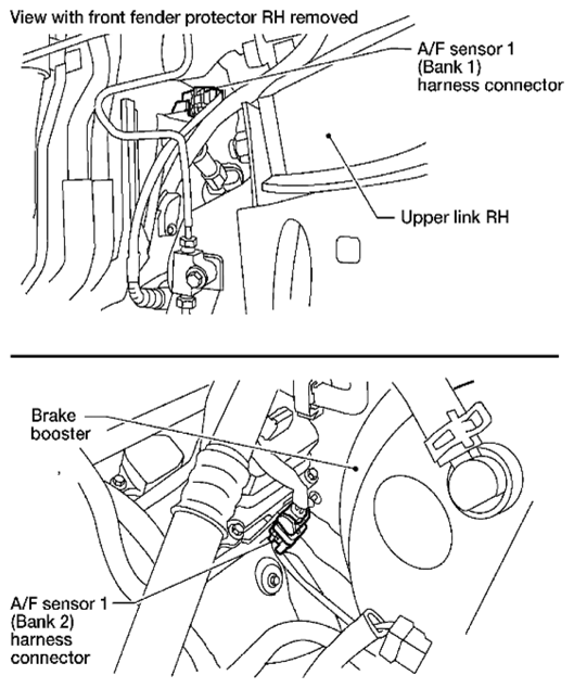
CHECK A/F SENSOR 1 INPUT SIGNAL
- Turn ignition switch OFF.
- Disconnect A/F sensor 1 harness connector.
   Courtesy of SUZUKI OF AMERICA CORP.SUZUKI OF AMERICA CORP.SUZUKI OF AMERICA CORP. Courtesy of SUZUKI OF AMERICA CORP.SUZUKI OF AMERICA CORP.SUZUKI OF AMERICA CORP.
- 3. Disconnect ECM harness connector.
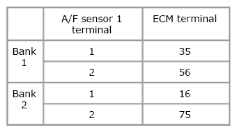
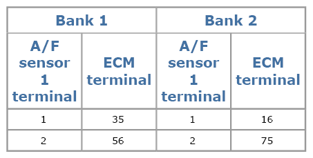
- 4. Check harness continuity between A/F sensor 1 terminal and ECM terminal as follows. Refer to WIRING DIAGRAM
.
Courtesy of SUZUKI OF AMERICA CORP.SUZUKI OF AMERICA CORP.SUZUKI OF AMERICA CORP.
Continuity should exist.
- 5. Check harness continuity between the following terminals and ground. Refer to WIRING DIAGRAM
.
Courtesy of SUZUKI OF AMERICA CORP.SUZUKI OF AMERICA CORP.SUZUKI OF AMERICA CORP.
Continuity should not exist.
- 6. Also check harness for short to power.
OK or NG |
GO TO 16. |
Repair open circuit or short to ground or short to power in harness or connectors between ECM and A/F sensor 1. |
| 16 |
CHECK A/F SENSOR 1 HEATER
Refer to
[P0031, P0032, P0051, P0052 A/F SENSOR 1 HEATER
].
OK or NG |
GO TO 18. |
GO TO 17. |
| 17 |
REPLACE A/F SENSOR 1
Replace malfunctioning A/F sensor 1. Refer to EXHAUST MANIFOLD AND THREE WAY CATALYST: EXPLODED VIEW [VQ40DE]
.
CAUTION:
- Discard any A/F sensor which has been dropped from a height of more than 0.5 m (19.7 in) onto a hard surface such as a concrete floor; use a new one.
- Before installing new A/F sensor, clean exhaust system threads using Heated Oxygen Sensor Thread Cleaner tool J-43897-18 or J-43897-12 and approved anti-seize lubricant.
|
INSPECTION END |
|
| 18 |
CHECK MASS AIR FLOW SENSOR
- With SDT
Check mass air flow sensor signal in "Data list" mode with SDT.
2.0 - 6.0 g/sec: at idling
7.0 - 20.0 g/sec: at 2, 500 RPM
- With GST
Check mass air flow sensor signal in Service $01 with GST.
2.0 - 6.0 g/sec: at idling
7.0 - 20.0 g/sec: at 2, 500 RPM
OK or NG |
GO TO 19. |
Check connectors for rusted terminals or loose connections in the mass air flow sensor circuit or ground. Refer to
[P0101 MAF SENSOR
]. |
| 19 |
CHECK SYMPTOM MATRIX CHART
Check items on the rough idle symptom in
[ENGINE CONTROL SYSTEM SYMPTOMS: SYMPTOM MATRIX CHART
].
OK or NG |
GO TO 20. |
Repair or replace. |
| 20 |
ERASE THE 1ST TRIP DTC
Some tests may cause a 1st trip DTC to be set. Erase the 1st trip DTC from the ECM memory after performing the tests. Erase the DTC memory. Refer to [On Board Diagnosis Function
] (Without SDT) or [SDT Function
] (With SDT). |
GO TO 21. |
|
| 21 |
CHECK INTERMITTENT INCIDENT
Refer to
[SERVICE INFORMATION FOR ELECTRICAL INCIDENT: WORK FLOW
] |
INSPECTION END |