Remove/install valves - AR05.30-P-3511SX
WARNING: This page does not describe the selected car, but rather 33 other vehicles, including the 2016 Mercedes-Benz E63 S AMG, 2016 Mercedes-Benz E400, 2016 Mercedes-Benz E350, 2016 Mercedes-Benz E300, and 2016 Mercedes-Benz E250. However, it is still accessible from the selected car via links, so may be relevant.
ENGINE 272, 273
Cylinder head removed
 Courtesy of MERCEDES-BENZ USA
 Courtesy of MERCEDES-BENZ USA
  |
Removing/installing |
|
|
 |
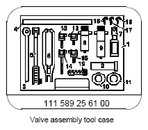
Assembly tool |
|
Figure |
|
Valve assembly tool case |
|
Figure |
|
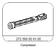
Compressor |
|
Fig 5 |
| 1 |
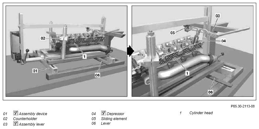
Mount cylinder head (1)
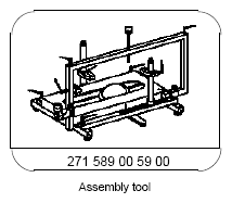
onto assembly device (01) |
 Before startup of assembly device
(01), check that the counterholders (02) are correctly mounted at cylinder head (1). There is a risk that the cylinder head (1) is pressed to the top out of the assembly device
(01), because the air bellows of the assembly device
(01) in the combustion chamber of the cylinder head (1) are pressed onto the valve disk.
Before startup of assembly device
(01), check that the counterholders (02) are correctly mounted at cylinder head (1). There is a risk that the cylinder head (1) is pressed to the top out of the assembly device
(01), because the air bellows of the assembly device
(01) in the combustion chamber of the cylinder head (1) are pressed onto the valve disk.
 Observe owner's manual of assembly device manufacturer
(01).
Observe owner's manual of assembly device manufacturer
(01). |
|
| 2 |
Mount assembly lever (03)
with depressor (04) onto sliding piece (05) |
Position depressor (04) vertically at upper valve spring plate (2) and align to sliding piece (05). |
|
| 3 |
Move the air bellows of the assembly device (01) with a lever (06) in such a way that the air bellows are matched with the combustion chamber of the respective valves |
Ensure, that the air bellows of the assembly device
(01) are correctly matched with a combustion chamber and pressed in centrally, otherwise the air bellows can press laterally out of the combustion chamber.
Observe owner's manual of assembly device manufacturer
(01). |
|
| 4 |
Connect compressed air to assembly device (01) and open compressed air valve |
Press the air bellows of the assembly device
(01) in the combustion chamber onto the valve disks.
Observe owner's manual of assembly device manufacturer
(01). |
|
| 5 |
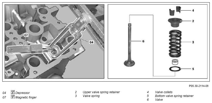
Remove upper valve spring plate (2) and valve spring (3) |
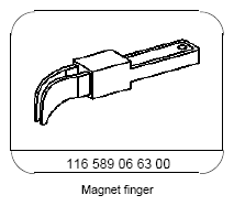
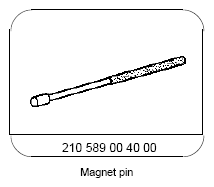
Compress valve spring (3). Remove split valve spring retainer locks (4)
with magnetic rod (07)  , magnetic pin or tweezers.
 |
|
| |
|
|
Figure |
| |
|
|
Figure |
| |
|
|
*WH58.30-Z-1040-02A |
| |
|
 Before mounting the upper valve spring plates (2) and valve springs (3), replace valve stem seals.
 |
AR05.30-P-3500-02VA |
| 6 |
Take out lower valve spring plate (5). |
|
|
| 7 |
Close compressed air valve and compressed air connection for
assembly device (01) |
|
|
| 8 |
Dismount cylinder head (1)
from assembly device (01) and take out valves (6) |
|
|
 |
Checking |
|
|
| 9 |
Inspect valve spring plate (2, 5) for pitting; replace if required |
|
|
| 10 |
Check valves (6) |
If the specified tolerances are below the limit, the valve must be replaced, in order to assure the function.
Check surface of valve stems for roughness and burrs (visual inspection or with nail).
Replace valves (6) with a rough stem surface or formation of burrs.
The valves must not be machined. |
AR05.30-P-4201-01VA |
| 11 |
Install in reverse order |
|
|
 Courtesy of MERCEDES-BENZ USA
 Courtesy of MERCEDES-BENZ USA
 Courtesy of MERCEDES-BENZ USA
 Courtesy of MERCEDES-BENZ USA
 Courtesy of MERCEDES-BENZ USA
 COMMERCIALLY AVAILABLE TOOLS
| Number |
Designation |
| WH58.30-Z-1040-02A |
Tweezers, straight 160 mm with rounded tips |