Transmission Fluid Pump Disassemble
 Courtesy of GENERAL MOTORS CORP.
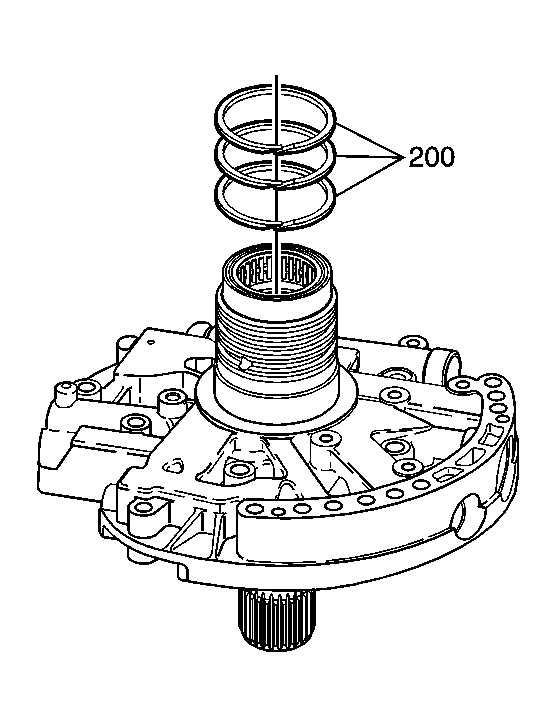
- Remove the reverse clutch housing seal rings (200).
 Courtesy of GENERAL MOTORS CORP.
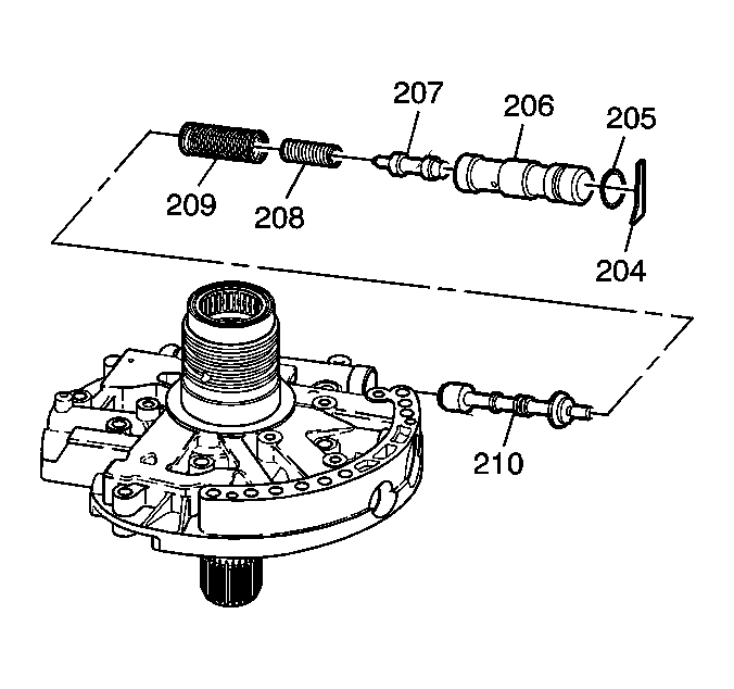
- Remove the line boost valve retainer (204).
- Remove the line boost valve bushing (206) and the line boost valve (207).
- Remove the line boost valve bushing seal (205).
- Remove the line boost valve spring (208) and the pressure regulator valve spring (209).
- Remove the pressure regulator valve (210).
 Courtesy of GENERAL MOTORS CORP.
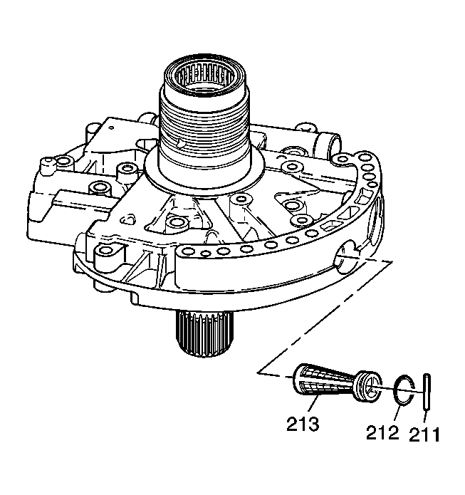
- Remove the fluid pump cover screen pin (211).
- Remove the fluid pump cover screen (213).
- Remove the fluid pump cover seal (212).
 Courtesy of GENERAL MOTORS CORP.
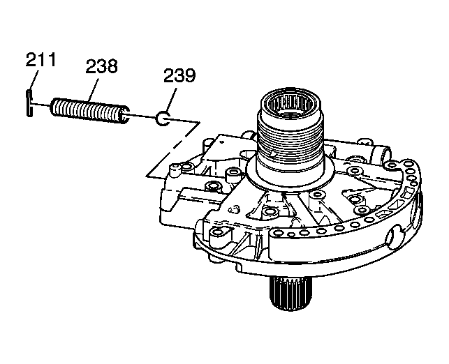
- Remove the pressure relief ball pin (211).
- Remove the pressure relief spring (238) and the pressure relief ball (239).
 Courtesy of GENERAL MOTORS CORP.
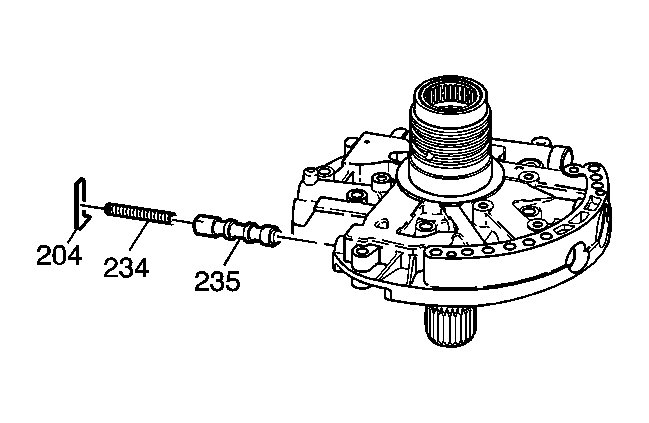
- Remove the torque converter clutch (TCC) control valve pin (204).
- Remove the TCC control valve spring (234) and the TCC control valve (235).
 Courtesy of GENERAL MOTORS CORP.
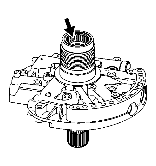
- Inspect the input shaft bearing (201) for the following:
- Damaged bearing cage
- Pitted bearings
- Scored bearings