Install / gauge the crankshaft bearings - AR03.20-P-4341-01VT
WARNING: This page does not describe the selected car, but rather 28 other vehicles, including the 2012 Mercedes-Benz GL550, 2012 Mercedes-Benz GL450, 2011 Mercedes-Benz ML63, 2011 Mercedes-Benz ML550, and 2011 Mercedes-Benz ML350. However, it is still accessible from the selected car via links, so may be relevant.
CHECK VALUES FOR CRANKSHAFT BEARING CLEARANCE
| Number |
Designation |
Engine 112 except 112.951/976, Engines 113.940/941/942/943/944/948/960/961/963/964/965/966/967/968/971/980/981/984/986 |
Engine 113.987/988/989 /990/991/993 |
| BE03.20-P-1001-04E |
Main bearing play |
radial when new |
mm |
0.026 to 0.050 |
0.026 to 0.050 |
| axial when new |
mm |
0.10 to 0.266 |
0.10 to 0.266 |
CRANKSHAFT BEARING CAP
| Number |
Designation |
Engines 112, 113 |
| BA03.20-P-1001-01D |
Crankshaft bearing cap bolt |
M8 |
Stage 1 |
Nm |
20 |
| Stage 2 |
∠° |
90 |
| BA03.20-P-1002-01D |
Side crankshaft bearing cap bolt |
M8 |
|
Nm |
30 |
| BA03.20-P-1003-01D |
Crankshaft bearing cap bolt |
M10 |
Stage 1 |
Nm |
5 |
| Stage 2 |
Nm |
30 |
| Stage 3 |
°∠ |
90 |
- Blow through oil galleries in direction of flow oil with compressed air.
- Clean the bearing points in the crankcase, main bearing cap and main bearing journal of crankshaft with a chamois leather.
 If a bearing damage has occurred, it may be necessary to remove any debris from the connecting rod bores, oil ducts, the crankshaft and crankcase casings as well as the crankcase! Do not use any hard objects for cleaning.
The top bearing shell halves are assigned to the basic journal of the crankshaft by means of a colored ring on the rear of the upper bearing shell half and numbers (arrows) or center punch marks, which are stamped into the crankcase.
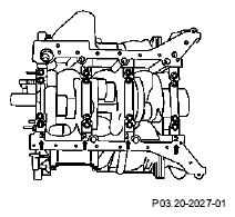 Courtesy of MERCEDES-BENZ OF NORTH AMERICA.
Only assigned color and numerical combinations (see table) may be fitted together.
| Assignment of crankshaft bearing shell top halves (crankcase) M 112, 113 |
| Diameter Main bearing bore in crankcase |
Number or chisel punches |
Color coding for bearing shell |
Order index |
Main bearing play (mm) |
| 68.500-68.506 |
1 |
blue |
52 |
0.030-0.052 |
| 68.506-68.513 |
2 |
yellow |
54 |
0.030-0.052 |
| 68.513-68.519 |
3 |
red |
56 |
0.030-0.052 |
| Assignment of crankshaft bearing shell bottom halves (bearing cap) M 112, 113 |
| Diameter Main bearing journal |
Laser inscription AM Crankshaft journal Front |
Color coding for bearing shell |
Order index |
Main bearing play (mm) |
| 63.940-63.945 |
V |
purple |
58 |
0.030-0.052 |
| 63.945-63.950 |
W |
white |
57 |
0.030-0.052 |
| 63.950-63.955 |
R |
red |
56 |
0.030-0.052 |
| 63.955-63.960 |
G |
yellow |
54 |
0.030-0.052 |
| 63.960-63.965 |
b |
blue |
52 |
0.030-0.052 |
The bottom halves of the bearing shells are assigned to the basic journal of the crankshaft by means of the first letter of the respective color.
The color coding of the bottom halves of the bearing shells is located at the rear of the lower bearing shell halves.
The initial letters of the particular colors are engraved on the journal of the crankshaft.
When installing the bearing shell halves, the order of the colors engraved on the journal of the crankshaft must be maintained.
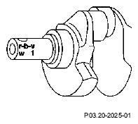 Courtesy of MERCEDES-BENZ OF NORTH AMERICA.
Arrow identifies direction of travel.
- First letter "r": A bearing cap with the color coding red must be inserted in bearing cap "1".
- Second letter "b": A bearing cap with the color coding blue must be inserted in bearing cap "2".
- Third letter "v": A bearing cap with the color coding violet must be inserted in bearing cap "3".
- Fourth letter "w": A bearing cap with the color coding white must be inserted in bearing cap "4".
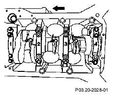 Courtesy of MERCEDES-BENZ OF NORTH AMERICA.
- Insert the bearing shell top halves (1) with oil drillings (2) and oil grooves (3) into the crankcase.
When doing this, ensure that the anti-twist locks (4) of the bearing shell halves (1) are located in the recesses of the crankcase.
- Insert the bearing shell bottom halves (7) into the bearing caps (6).
When doing this, ensure that the anti-twist locks (5) of the bottom bearing shell halves (7) are located in the recesses of the bearing caps (6).
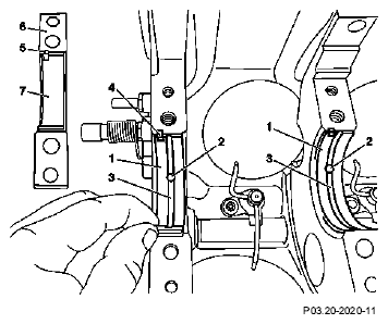 Courtesy of MERCEDES-BENZ OF NORTH AMERICA.
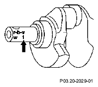
- The thrust plates are assigned to the bearing caps (6) using the numbers "1" and "0" (see table). These are engraved on the journal of the crankshaft (arrowed).
The thrust washers installed must have the same designation.
 Courtesy of MERCEDES-BENZ OF NORTH AMERICA.
| Assignment of thrust washers to crankshaft M 112, 113 |
| Crankcase |
Basic journal of the fitted bearing of the crankshaft |
Thrust washers |
Axial play Crankshaft (mm) |
| |
Inscription |
Designation |
Marking |
| No subdivision |
N |
0 |
N |
Abbreviated reference number |
0, 10-0, 266 |
| No subdivision |
N1 |
1 |
N1 |
Abbreviated reference number |
0.10-0.266 |
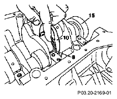
- Insert crankshaft (15) into crankcase
- Install top thrust washers (8).
The oil grooves (9) of the thrust plates (8) must point toward the crank webs (10).
 Courtesy of MERCEDES-BENZ OF NORTH AMERICA.
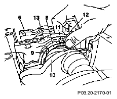
- Install bearing caps (6) according to their markings.
Installation:
When installing the fit bearing cap (13), hold both thrust plates (8) tight. The anti-twist locks (11) of the thrust plates (8) must be located in the slots (12) of the fit bearing cap (13). The oil grooves (9) of the thrust plates (8) must point toward the crank webs (10).
 Courtesy of MERCEDES-BENZ OF NORTH AMERICA.
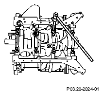
- Moisten the thread and head contact surface of the bolts of the bearing caps with oil.
- Tighten the bolts of the bearing caps as specified in the tightening pattern.

Note tightening torque and tightening angle of bearing cap bolts. If no torquing angle wrench is available, the bearing cap bolts can be torqued further by the specified angle in a single operation using a wrench and locking handle. Do not use a flexi-rod torque wrench for tightening in order to avoid any angle errors.
- Turn crankshaft to check for unobstructed movement.
 Courtesy of MERCEDES-BENZ OF NORTH AMERICA.