Mount connecting rod bearing - AR03.10-P-6111-08SX
WARNING: This page does not describe the selected car, but rather 28 other vehicles, including the 2012 Mercedes-Benz GL550, 2012 Mercedes-Benz GL450, 2011 Mercedes-Benz ML63, 2011 Mercedes-Benz ML550, and 2011 Mercedes-Benz ML350. However, it is still accessible from the selected car via links, so may be relevant.
INSPECTION DATA FOR CRANKSHAFT BEARING CLEARANCE
| Number |
Designation |
Engine 273 |
| BE03.20-P-1002-04E |
Connecting rod bearing play |
radial when new |
mm |
0.022...0.066 |
CONNECTING ROD
| Number |
Designation |
Engine 273 |
| BA03.10-P-1001-01E |
Connecting rod bolt |
Stage 1 |
Nm |
5 |
| Stage 2 |
Nm |
25 |
| Stage 3 |
∠ ° |
90 |
| Assignment of connecting rod bearing to connecting rod journal for engine 273 |
| Upper half of connecting rod |
Lower half of connecting rod bearing cap |
Connecting rod bearing play (mm) |
| yellow |
yellow |
0.022...0.066 |
| blue |
red |
0.022...0.066 |
| red |
blue |
0.022...0.066 |
- Clean bearing points on connecting rod, connecting rod bearing caps and connecting rod journals with a chamois leather.
 Blow through oil ducts in direction of flow oil with compressed air. Do not use any hard objects for cleaning.
- The assignment of connecting rods to the connecting rod bearing journals is indicated on the back of the connecting rod bearing shells by a colored dot.
Only assigned color combinations of the connecting rod bearing shells (see table) may be installed together. The sequence of the individual color combinations on the connecting rod bearing journals can be selected at random.
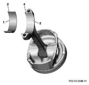
- Insert connecting rod bearing shells (1) into connecting rod (2) and connecting rod bearing cap.
 The anti-twist locks (3) of the connecting rod bearing shells (1) must be located in the cutouts (4) of the connecting rod (2) and the connecting rod bearing cap.
 Courtesy of MERCEDES-BENZ OF NORTH AMERICA.
- Install connecting rod bearing cap with connecting rod bearing shells (1).
- Spread engine oil onto the thread and bolt head contact surface of the connecting rod bolts.
- Screw in connecting rod bolts and tighten to step 1.
- Tighten connecting rod bolts to step 2.
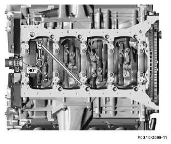
- Tighten connecting rod bolts using an angle wrench to Stage 3.
If no torquing angle wrench is available, the connecting rod screws can be torqued further by the specified angle in a single operation using a wrench and tommy bar.
Do not use a flexi-rod torque wrench for tightening in order to avoid any angle errors.
 Courtesy of MERCEDES-BENZ OF NORTH AMERICA.