Removing and installing steering knuckle - AR33.25-P-0400A
WARNING: This page does not describe the selected car, but rather 42 other vehicles, including the 1999 Mercedes-Benz S600, 1999 Mercedes-Benz S500, 1999 Mercedes-Benz S420, 1999 Mercedes-Benz S320, and 1999 Mercedes-Benz CL600. However, it is still accessible from the selected car via links, so may be relevant.
MODEL 140
 Courtesy of MERCEDES-BENZ OF NORTH AMERICA.
  |
Removing, installing |
|
|
 |
To remove the steering knuckle the shock absorber must be installed |
|
|
| Installation |
Replace self-locking nuts and bolts |
|
|
| 1 |
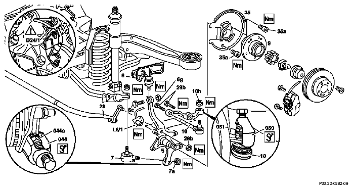
Remove front wheel hub (9) |
|
AR33.20-P-0310A |
| 2 |
Remove brake caliper dust shield (35) |
 |
*BA42.10-P-1003-06A |
| 3 |
Detach torsion bar connecting rod (28) from steering knuckle (5) |
|
*BA32.20-P-1001-02B |
| 4 |
Remove speed sensor (L6/1) and brake lining wear indicator |
Expose the cables. |
*BA42.30-P-1001-01A |
| 5 |
In vehicles with ADS, remove wheel acceleration sensor (B24/1) |
The acceleration sensor (B24/1) is sensitive to shocks. |
|
| 6 |
Detach tie rod (10) from steering knuckle arm |
 Check rubber boot and ball joint for wear and damage.
 |
*BA46.40-P-1001-01A |
| |
|
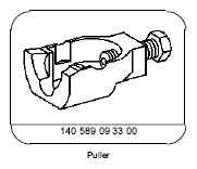
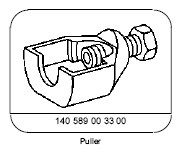
 Puller (050)
 |
Figure |
| |
|
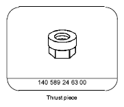
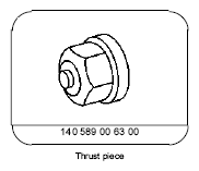
Thrust piece (051) |
Figure |
| 7 |
Remove supporting joint (7) from steering knuckle (5) |
Check rubber boot and ball joint for wear and damage. |
*BA33.20-P-1004-01A |
| |
|
Puller (044) |
Figure |
| |
|
Thrust piece (044a) |
Figure |
| 8 |
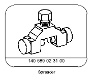
Detach steering knuckle (5) from upper wishbone (6) |
Check rubber boot and ball joint for wear and damage. |
AR33.25-P-0500-01A |
| |
|
|
*BA33.20-P-1001-01A |
| |
|
|
Figure |
| 9 |
Remove steering knuckle arm |
|
*BA33.20-P-1005-01A |
|
Checking |
|
|
| 10 |
Check supporting joint |
|
AR33.20-P-0425A |
| 11 |
Check steering knuckle if necessary |
|
AR40.30-P-0451B |
| 12 |
Install in the reverse order |
|
|
| 13 |
Carry out chassis alignment check. |
 After installation of new parts.
 |
AR40.20-P-0200A |
FRONT AXLE TORSION BAR
| Number |
Designation |
Model 140 up to 10/95 |
Model 140 as of 10/95 |
| BA32.20-P-1001-02B |
Self-locking nut, connecting rod to steering knuckle |
Nm |
40 |
40 |
WHEEL LOCATION, HUB
| Number |
Designation |
Model 140 |
| BA33.20-P-1001-01A |
Self-locking nut, clamp connection of upper wishbone to steering knuckle |
Nm |
125 |
| BA33.20-P-1004-01A |
Self-locking nut, supporting joint to steering knuckle |
Nm |
140 |
| BA33.20-P-1005-01A |
Bolt, steering knuckle arm to steering knuckle |
Nm |
80 |
BRAKE DISCS, BRAKE CALIPER DUST SHIELD
| Number |
Designation |
Model 140 |
| BA42.10-P-1003-06A |
Bolt, brake caliper dust shield on steering knuckle |
Nm |
22 |
FRONT AXLE SPEED SENSOR
| Number |
Designation |
Model 140 |
| BA42.30-P-1001-01A |
Self-locking bolt, front axle speed sensor to steering knuckle |
Nm |
22 |
TIE ROD
| Number |
Designation |
Model 140 |
| BA46.40-P-1001-01A |
Self-locking nut, tie rod to pitman arm |
Nm |
50 |
 Courtesy of MERCEDES-BENZ OF NORTH AMERICA.
 Courtesy of MERCEDES-BENZ OF NORTH AMERICA.
 Courtesy of MERCEDES-BENZ OF NORTH AMERICA.
 Courtesy of MERCEDES-BENZ OF NORTH AMERICA.
 Courtesy of MERCEDES-BENZ OF NORTH AMERICA.