Test F: Speedometer/Odometer Inoperative (With Rear Anti-Lock Brakes)
- Connect NGS tester to Data Link Connector (DLC). Monitor PID IGN_GEM while turning ignition switch to each position. If PID values agree with key positions, go to next step. If PID values do not agree with key positions, see appropriate STEERING COLUMN SWITCHES article.
- Retrieve and record continuous DTCs. Clear continuous DTCs. Perform GEM on-demand self-test. If DTC C1751 exists, go to step 9. If DTC C1752 exists, go to step 7. If DTC P0500 or no DTCs exist, go to next step.
- Disconnect Generic Electronic Module (GEM) harness connector T-224. Disconnect Rear Anti-lock Brake (RABS) module harness connector. See Fig 4. Disconnect RABS sensor harness connector. Measure resistance between ground and terminal No. 9 (Red/Pink wire) at GEM harness connector T-224. See Fig 3. Measure resistance between ground and terminal No. 18 (Light Green/Black wire) at GEM harness connector T-224. If any resistance reading is 10 k/ohms or less, repair short to ground in Red/Pink wire or Light Green/Black wire. If all resistance readings are greater than 10 k/ohms, go to next step.
- Measure resistance in Red/Pink wire between RABS sensor harness connector and terminal No. 9 at GEM harness connector T-224. Measure resistance in Light Green/Black wire between RABS sensor harness connector and terminal No. 18 at GEM harness connector T-224. If any resistance reading is greater than 5 ohms, repair open in Red/Pink wire or Light Green/Black wire. If all resistance readings are 5 ohms or less, go to next step.
- Turn ignition switch to RUN position. Measure voltage at terminal No. 9 (Red/Pink wire) at GEM harness connector T-224. Measure voltage at terminal No. 18 (Light Green/Black wire) at GEM harness connector T-224. If voltage exists, repair short to voltage in appropriate wire. If voltage does not exist, go to next step.
- Connect GEM harness connectors. Ensure RABS sensor is still disconnected. Using NGS tester, monitor PID VSS_GEM while driving 0-55 MPH. If PID VSS_GEM value is greater than zero MPH, go to next step. If PID VSS_GEM value is zero MPH, test RABS sensor. See appropriate ANTI-LOCK article in BRAKES. If RABS sensor is okay, replace GEM.
- Turn ignition switch to LOCK position. Remove instrument cluster and disconnect harness connectors. Disconnect Powertrain Control Module (PCM) harness connectors. Disconnect cruise control servo harness connector. Disconnect Generic Electronic Module (GEM) harness connector T-224. Measure resistance between ground and terminal No. 1 (Gray/Black wire) at GEM harness connector T-224. See Fig 3. If resistance is 10 k/ohms or less, repair short to ground in Gray/Black wire. If resistance is greater than 10 k/ohms, go to next step.
- Measure resistance of Gray/Black wire between terminal No. 1 at instrument cluster harness connector C-215 and terminal No. 1 at GEM harness connector T-224. See Figure and Fig 3
. If resistance is greater than 5 ohms, repair open in Gray/Black wire. If resistance is 5 ohms or less, go to next step.
- Disconnect instrument panel harness connectors C-214, C-215 and C-216. Disconnect GEM harness connector T-224. Turn ignition switch to RUN position. Measure voltage at terminal No. 1 (Gray/Black wire) at GEM harness connector T-224. If voltage is greater than 10 volts, repair short to voltage in Gray/Black wire. If voltage is 10 volts or less, go to next step.
- Turn ignition switch to LOCK position. Measure voltage at terminal No. 7 (White/Yellow wire) at instrument cluster harness connector C-216. See Figure. If voltage is greater than 10 volts, go to next step. If voltage is 10 volts or less, repair open White/Yellow wire.
- Check printed circuit by making measurements at speedometer gauge pins, inside instrument cluster printed circuit clips. See SPEEDOMETER PRINTED CIRCUIT MEASUREMENTS table. If all resistance readings are one ohm or less, replace speedometer. If any resistance reading is greater than one ohm, replace instrument cluster printed circuit.
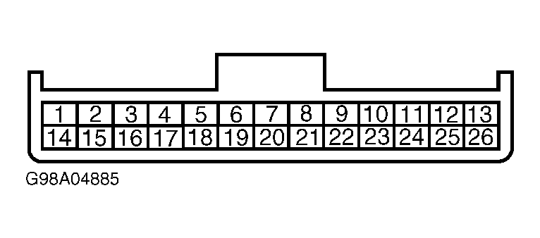 Courtesy of MAZDA MOTORS CORP.
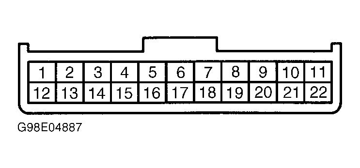 Courtesy of MAZDA MOTORS CORP.
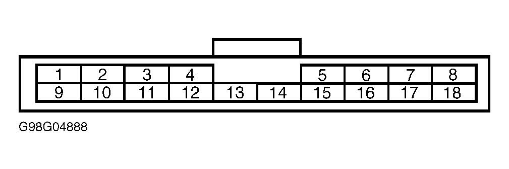 Courtesy of MAZDA MOTORS CORP.
 Courtesy of MAZDA MOTORS CORP.