Test Ac: Message Center Switch Not Operating Properly
- Turn ignition switch to LOCK position. Connect New Generation Star (NGS) tester to Data Link Connector (DLC). DLC is located below left side of instrument panel, to right of steering column. Turn ignition switch to RUN position. Using NGS tester, retrieve and record continuous Message Center Module (MCM) DTCs. Clear MCM DTCs. Using NGS tester, perform MCM self-test. If no MCM DTCs are retrieved, go to next step. If MCM DTC B1205 is retrieved, go to step 3
. If any other MCM DTCs are retrieved, repair code related problem. See MESSAGE CENTER MODULE DIAGNOSTIC TROUBLE CODE INDEX
table under SELF-DIAGNOSTIC SYSTEM.
- Using NGS tester, monitor MCM PIDs FUELSW, RESETSW, SETUPSW and STATUSSW while pressing each message center button. If PIDs do not agree with all switch positions, go to next step. If PIDs agree with all switch positions, replace instrument cluster.
- Turn ignition switch to LOCK position. Disconnect instrument cluster 22-pin harness connector C220a. Disconnect message center switch 6-pin harness connector C253. Measure resistance in Brown/White wire between message center switch harness connector C253 terminal No. 6 and instrument cluster harness connector C220a terminal No. 12. See Figure
and Fig 1
. Resistance should be 5 ohms or less. Measure resistance between ground and instrument cluster harness connector C220a terminal No. 12 (Brown/White wire). Resistance should be more than 10 k/ohms. If both resistances are as specified, go to next step. If either resistance is not as specified, repair open or short to ground in Brown/White wire between instrument cluster and message center switch.
- Measure resistance in Yellow/Violet wire between message center switch harness connector C253 terminal No. 3 and instrument cluster harness connector C220a terminal No. 13. Resistance should be 5 ohms or less. Measure resistance between ground and instrument cluster harness connector C220a terminal No. 13 (Yellow/Violet wire). Resistance should be more than 10 k/ohms. If both resistances are as specified, replace message center switch. If either resistance is not as specified, repair open or short to ground in Yellow/Violet wire between instrument cluster and message center switch.
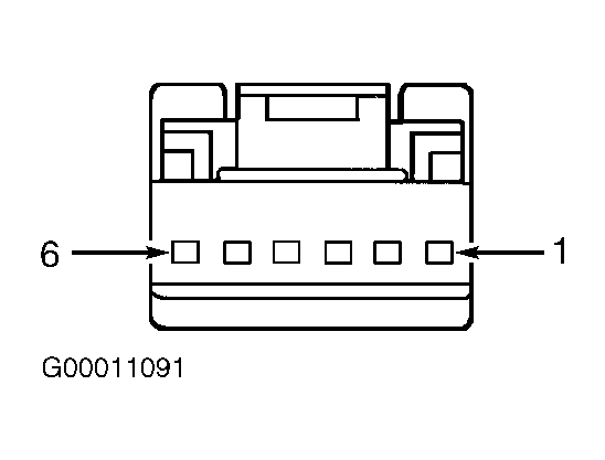 Courtesy of FORD MOTOR CO.