Part 2
1UR-FE ENGINE CONTROL: SFI SYSTEM: P1603, P1605: Engine Stall History
P1605 - Rough Idling
21. INSPECT FUEL PUMP
(a) Inspect the fuel pump Fuel Pump.
NG -- REPLACE FUEL PUMP Removal
OK -- CHECK FUEL PUMP CONTROL SYSTEM Fuel Pump Control Circuit
22. CHECK FUEL SYSTEM
(a) Check for foreign matter, such as iron particles, around the fuel pump, fuel pump filter and inside the fuel tank, and for signs that the fuel pump was stuck.
Result

HINT
If there is foreign matter such as iron particles on the fuel pump, fuel filter or fuel tank, remove the foreign matter.
B -- REPLACE MALFUNCTIONING PARTS
A -- REPAIR OR REPLACE FUEL SYSTEM
23. READ FREEZE FRAME DATA
(a) Connect the Techstream to the DLC3.
(b) Turn the engine switch on (IG).
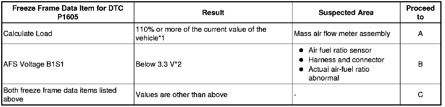
(c) Using the Techstream, confirm the vehicle conditions recorded in the freeze frame data which were present when the DTC was stored Freeze Frame Data.
Result
HINT
- Try to operate the vehicle under the conditions recorded in the freeze frame data which were present when the malfunction occurred. Confirm the data at this time and the data when the engine is idling (engine warmed up, no load, and shift lever in D or N) and compare these data with the freeze frame data.
- *1: If the mass air flow meter is malfunctioning and incorrectly measures the intake air volume to be higher than the actual volume of air flowing through the intake manifold, the freeze frame data will show a high engine load value.
- *2: As the air fuel ratio sensor output is low before the sensor warms up, the value at that time cannot be used for diagnosis. If the air fuel ratio sensor is malfunctioning and constantly outputs a value indicating the air-fuel ratio is rich, the actual air-fuel ratio will become lean and the engine may stall.
C -- READ FREEZE FRAME DATA
B -- PERFORM ACTIVE TEST USING TECHSTREAM (CONTROL THE INJECTION VOLUME)
A -- Continue to next step.
24. CHECK MASS AIR FLOW METER ASSEMBLY
(a) Remove the mass air flow meter assembly.
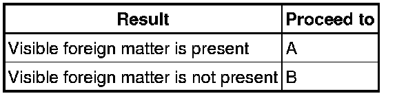
(b) Check for foreign matter in the airflow passage of the mass air flow meter.
Result
HINT
Even if the results are normal, the mass air flow meter may have been malfunctioning. Continue this inspection procedure until step 32, and if there are no problems with other parts, replace the mass air flow meter assembly (refer to step 57).
B -- READ FREEZE FRAME DATA
A -- REPLACE MASS AIR FLOW METER ASSEMBLY Removal
25. PERFORM ACTIVE TEST USING TECHSTREAM (CONTROL THE INJECTION VOLUME)
(a) Connect the Techstream to the DLC3.
(b) Turn the engine switch on (IG).
(c) Start the engine, turn off all accessory switches and warm up the engine until the engine coolant temperature stabilizes.
(d) Idle the engine.
(e) Enter the following menus: Powertrain / Engine and ECT / Active Test / Control the Injection Volume.
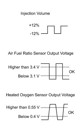
(f) Read the output voltage from the air fuel ratio sensor when increasing and decreasing the fuel injection volume.
Standard:

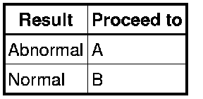
Result
HINT
- The air fuel ratio sensor has an output delay of a few seconds and the heated oxygen sensor has a maximum output delay of approximately 20 seconds.
- Even if the results are normal, the air fuel ratio sensor may have been malfunctioning. Continue this inspection procedure until step 32, and if there are no problems with other parts, replace the air fuel ratio sensor (refer to step 57).
B -- READ FREEZE FRAME DATA
A -- Continue to next step.
26. CHECK TERMINAL VOLTAGE (AIR FUEL RATIO SENSOR POWER SOURCE)
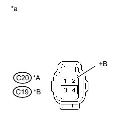
(a) Disconnect the air fuel ratio sensor connector.
(b) Turn the engine switch on (IG).
(c) Measure the voltage according to the value(s) in the table below.
Standard Voltage:

Text in Illustration
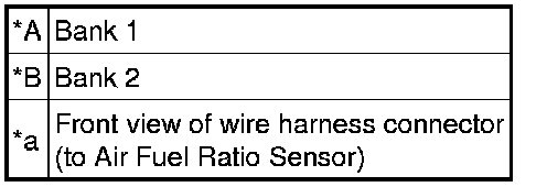
HINT
- Jiggle the wire harness and connector to increase the likelihood of detecting malfunctions that do not always occur.
- Make sure there is not an excessive amount of force applied to the wire harness.
NG -- REPAIR POWER SOURCE CIRCUIT P0031
OK -- Continue to next step.
27. CHECK HARNESS AND CONNECTOR (AIR FUEL RATIO SENSOR - ECM)
(a) Disconnect the air fuel ratio sensor connector.
(b) Disconnect the ECM connector.
(c) Measure the resistance according to the value(s) in the table below.
Standard Resistance:
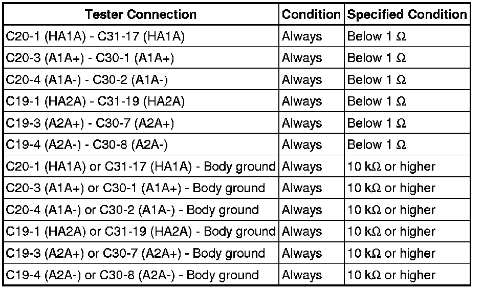
HINT
- Jiggle the wire harness and connector to increase the likelihood of detecting malfunctions that do not always occur.
- Make sure there is not an excessive amount of force applied to the wire harness.
NG -- REPAIR OR REPLACE HARNESS AND CONNECTOR
OK -- REPLACE AIR FUEL RATIO SENSOR Removal
28. READ FREEZE FRAME DATA
(a) Connect the Techstream to the DLC3.
(b) Turn the engine switch on (IG).
(c) Using the Techstream, confirm the vehicle conditions recorded in the freeze frame data which were present when the DTC was stored Freeze Frame Data.
Result

HINT
- *1: A long time had elapsed after stopping the engine.
- *2: A long time had not elapsed after stopping the engine.
B -- READ FREEZE FRAME DATA
A -- Continue to next step.
29. READ FREEZE FRAME DATA
(a) Connect the Techstream to the DLC3.
(b) Turn the engine switch on (IG).
(c) Using the Techstream, confirm the vehicle conditions present when the DTC was stored which are recorded in the freeze frame data.
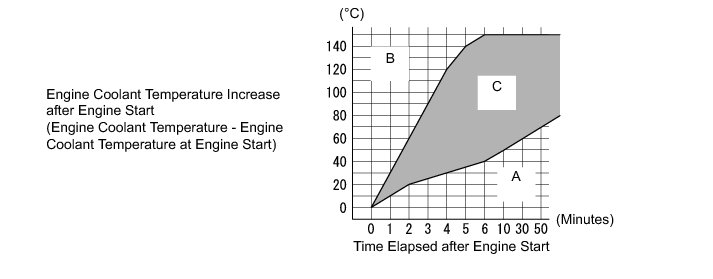
Result

HINT
This step is not directly related to engine stall.
C -- CLEAR DTC
B -- INSPECT ENGINE COOLANT TEMPERATURE SENSOR
A -- Continue to next step.
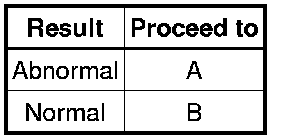
30. INSPECT THERMOSTAT
HINT
For the thermostat inspection, refer to the following procedures Testing and Inspection.
Result
HINT
This step is not directly related to engine stall.
B -- INSPECT ENGINE COOLANT TEMPERATURE SENSOR
A -- REPLACE THERMOSTAT Removal
31. READ FREEZE FRAME DATA
(a) Connect the Techstream to the DLC3.
(b) Turn the engine switch on (IG).
(c) Using the Techstream, confirm the vehicle conditions recorded in the freeze frame data which were present when the DTC was stored Freeze Frame Data.
Result

B -- CLEAR DTC
A -- Continue to next step.
32. INSPECT ENGINE COOLANT TEMPERATURE SENSOR
HINT
For the engine coolant temperature sensor inspection, refer to the following procedures Testing and Inspection.
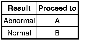
Result
HINT
Even if the results are normal, the engine coolant temperature sensor may have been malfunctioning. If there are no problems with other parts, replace the engine coolant temperature sensor (refer to step 57).
B -- REPLACE MALFUNCTIONING PARTS
A -- REPLACE ENGINE COOLANT TEMPERATURE SENSOR Removal
33. READ FREEZE FRAME DATA
(a) Connect the Techstream to the DLC3.
(b) Turn the engine switch on (IG).
(c) Using the Techstream, confirm the vehicle conditions recorded in the freeze frame data which were present when the DTC was stored Freeze Frame Data.
Result

HINT
- Try to operate the vehicle under the conditions recorded in the freeze frame data which were present when the malfunction occurred. Confirm the data at this time and the data when the engine is idling (engine warmed up, no load, and shift lever in D or N) and compare these data with the freeze frame data.
- *1: If the throttle body assembly has a temporary problem in which it cannot fully close, the intake air volume and engine speed increase. As a result, the ISC compensation amount becomes less than the standard. At this time, if the throttle body assembly returns to normal and fully closes, the intake air volume will be insufficient and the engine may stall.
- *2: If carbon accumulates on the throttle body assembly and the intake air volume decreases, the ISC compensation amount is increased to maintain the idling speed. If this situation continues, the ISC compensation amount reaches the upper limit, the idling speed cannot be maintained causing idling to become unstable, and the engine may stall.
C -- PERFORM ACTIVE TEST USING TECHSTREAM (CONTROL THE VVT SYSTEM)
B -- CHECK THROTTLE BODY ASSEMBLY
A -- Continue to next step.
34. CHECK THROTTLE BODY ASSEMBLY
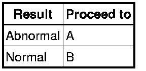
(a) Check for foreign matter and signs that the throttle body was stuck, and also check that the valve and shaft move smoothly during operation.
Result
HINT
Even if the results are normal, the throttle body may have been malfunctioning. Continue this inspection procedure until step 42, and if there are no problems with other parts, replace the throttle body assembly (refer to step 57).
B -- PERFORM ACTIVE TEST USING TECHSTREAM (CONTROL THE VVT SYSTEM)
A -- REPLACE THROTTLE BODY ASSEMBLY Removal
35. CHECK THROTTLE BODY ASSEMBLY
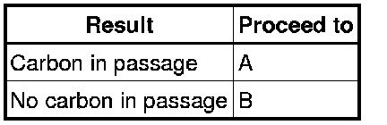
(a) Check if carbon is in the airflow passage of the throttle body.
Result
HINT
Even if the results are normal, the throttle body may have been malfunctioning. Continue this inspection procedure until step 42, and if there are no problems with other parts, replace the throttle body assembly (refer to step 57).
B -- PERFORM ACTIVE TEST USING TECHSTREAM (CONTROL THE VVT SYSTEM)
A -- REPLACE THROTTLE BODY ASSEMBLY Removal
36. PERFORM ACTIVE TEST USING TECHSTREAM (CONTROL THE VVT SYSTEM)
(a) Connect the Techstream to the DLC3.
(b) Turn the Techstream on.
(c) Warm up the engine.
(d) Enter the following menus: Powertrain / Engine and ECT / Active Test / Control the VVT System (Bank 1) or Control the VVT System (Bank 2).
HINT
When performing the Active Test, make sure the A/C is on and the shift lever is in N or P.
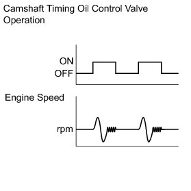
(e) Check the engine speed while operating the camshaft timing oil control valve using the Techstream.
OK:

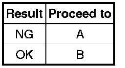
Result
HINT
- Jiggle the wire harness and connector to increase the likelihood of detecting malfunctions that do not always occur.
- When the results of the inspection using the Active Test are normal but the valve operating noise is abnormal, check the valve for any signs of problems.
- If the camshaft timing oil control valve is stuck ON, the valve overlap increases and combustion worsens due to the internal EGR which may cause rough idle or cause the engine to stall.
NG -- REPLACE CAMSHAFT TIMING OIL CONTROL VALVE ASSEMBLY Removal
OK -- Continue to next step.
37. PERFORM ACTIVE TEST USING TECHSTREAM (CONTROL THE VVT EXHAUST LINEAR)
(a) Connect the Techstream to the DLC3.
(b) Turn the Techstream on.
(c) Warm up the engine.
(d) Enter the following menus: Powertrain / Engine and ECT / Active Test / Control the VVT Exhaust Linear (Bank1) or Control the VVT Exhaust Linear (Bank2).
HINT
When performing the Active Test, make sure the A/C is on and the shift lever is in N or P.
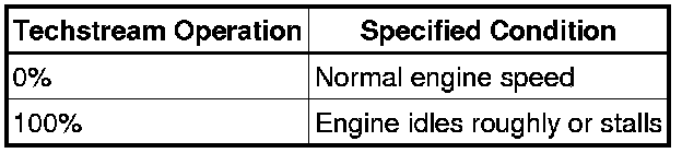
(e) Check the engine speed while operating the camshaft timing oil control valve using the Techstream.
OK:
HINT
- Jiggle the wire harness and connector to increase the likelihood of detecting malfunctions that do not always occur.
- When the results of the inspection using the Active Test are normal but the valve operating noise is abnormal, check the valve for any signs of problems.
- If the camshaft timing oil control valve is stuck ON, the valve overlap increases and combustion worsens due to the internal EGR which may cause rough idle or cause the engine to stall.
NG -- REPLACE CAMSHAFT TIMING OIL CONTROL VALVE ASSEMBLY Removal
OK -- Continue to next step.
38. PERFORM ACTIVE TEST USING TECHSTREAM (CONTROL THE EGR STEP POSITION)
(a) Connect the Techstream to the DLC3.
(b) Start the engine and warm it up until the engine coolant temperature reaches 75°C (167°F) or higher.
HINT
- When performing the Active Test, make sure the shift lever is in P or N.
- The A/C switch and all accessory switches should be off.
(c) Turn the Techstream on.
(d) Enter the following menus: Powertrain / Engine and ECT / Active Test / Control the EGR Step Position.
(e) Confirm that Throttle Idle Position is ON and check the engine idling condition and the value of MAP in the Data List while performing the Active Test.
HINT
- Do not leave the EGR valve open for 10 seconds or more during the Active Test.
- Be sure to return the EGR valve to step 0 when the Active Test is completed.
OK:
MAP and idling condition change in response to EGR step position as follows.
Standard:

NG -- INSPECT EGR VALVE ASSEMBLY
OK -- CHECK FREEZE FRAME DATA
39. INSPECT EGR VALVE ASSEMBLY
(a) Remove the EGR valve assembly Removal.
(b) Check if the EGR valve is stuck open.
OK:
EGR valve is tightly closed.
NG -- REPLACE EGR VALVE ASSEMBLY Removal
OK -- Continue to next step.
40. CHECK FREEZE FRAME DATA
(a) Connect the Techstream to the DLC3.
(b) Turn the engine switch on (IG).
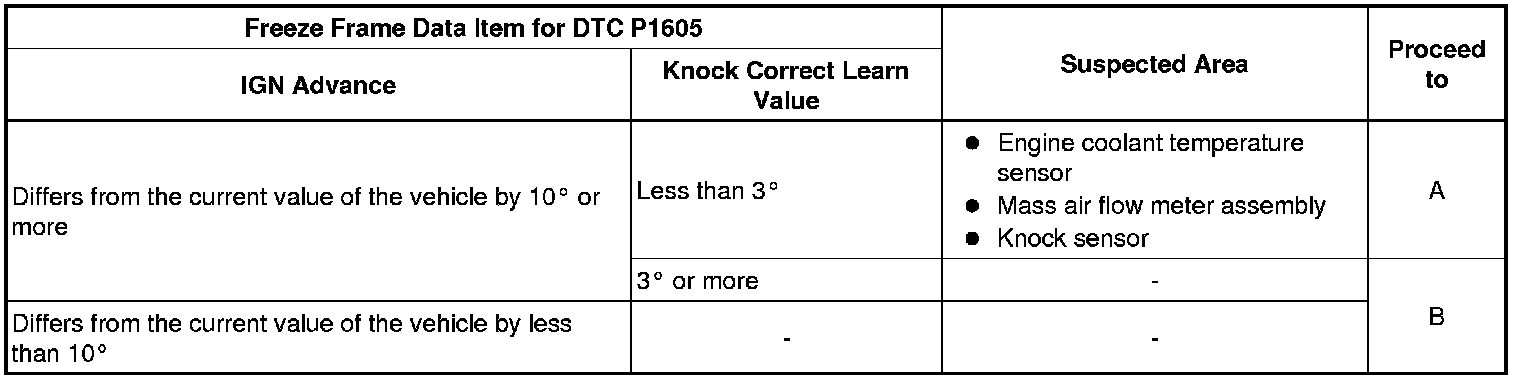
(c) Using the Techstream, confirm the vehicle conditions recorded in the freeze frame data which were present when the DTC was stored Freeze Frame Data.
Result
HINT
- Try to operate the vehicle under the conditions recorded in the freeze frame data which were present when the malfunction occurred. Confirm the data at this time and the data when the engine is idling (engine warmed up, no load, and shift lever in D or N) and compare these data with the freeze frame data.
- Even if the results are normal, the knock sensors may have been malfunctioning. If there are no problems with other parts, replace the knock sensors (refer to step 57).
B -- REPLACE MALFUNCTIONING PARTS
A -- Continue to next step.