Installation
FRONT SUSPENSION: FRONT SHOCK ABSORBER: INSTALLATION
HINT:
- Use the same procedures for the RH side and LH side.
- The procedures listed below are for the LH side.
- A bolt without a torque specification is shown in the standard bolt chart Standard Bolt - Specified Torque For Standard Bolts.
1. TEMPORARILY INSTALL FRONT SHOCK ABSORBER WITH COIL SPRING
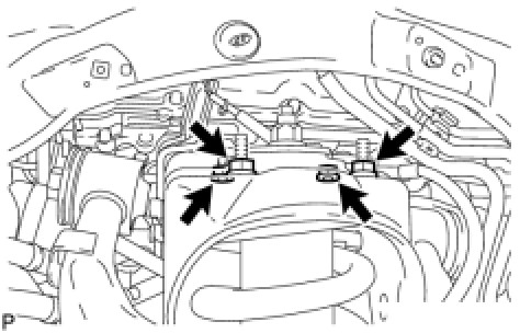
(a) Temporarily install the upper side of the shock absorber to the chassis frame with the 4 nuts.
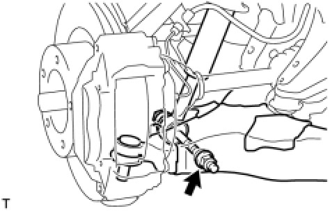
(b) Temporarily install the lower side of the shock absorber to the lower suspension arm with the bolt and nut.
2. CONNECT NO. 2 SUSPENSION CONTROL PRESSURE HOSE
(a) Apply MP grease to the O-ring and back-up ring of the suspension control pressure hose.
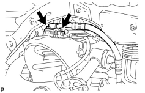
(b) Connect the suspension control pressure hose to the shock absorber with the 2 bolts.
Torque: 18 Nm (184 kgf-cm, 13 ft-lbf)
NOTICE:
Do not allow any foreign matter such as dirt and dust to enter the suspension control pressure hose from the connecting point.
3. BLEED AIR FROM SUSPENSION FLUID Service and Repair
4. CHECK FLUID LEVEL IN RESERVOIR Suspension Control System
5. INSPECT FOR SUSPENSION FLUID LEAK Suspension Control System
6. CONNECT STEERING KNUCKLE LH Installation
7. CONNECT SKID CONTROL SENSOR WIRE Installation
8. INSTALL FRONT FENDER APRON SEAL REAR LH
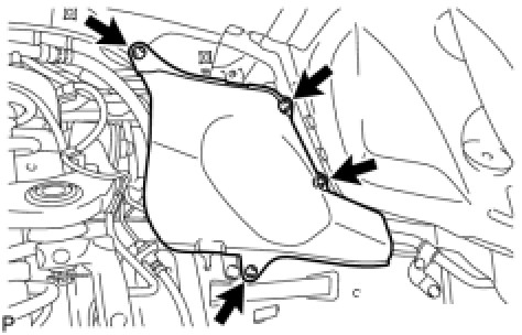
(a) Install the apron seal with the 4 clips.
9. INSTALL FRONT FENDER APRON SEAL LH
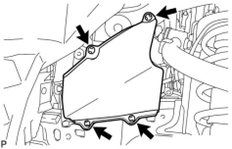
(a) Install the apron seal with the 4 clips.
10. TEMPORARILY INSTALL FRONT STABILIZER LINK ASSEMBLY LH
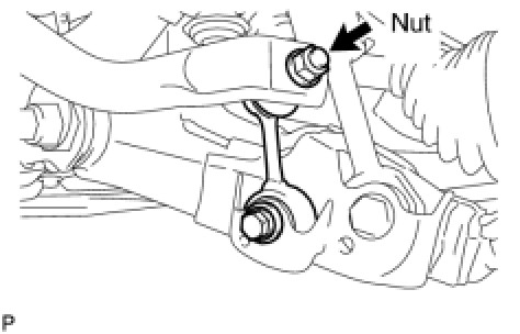
(a) Temporarily install the stabilizer link with the nut and bolt.
(b) Tighten the nut.
Torque: 128 Nm (1305 kgf-cm, ft-lbf)
11. TEMPORARILY INSTALL FRONT STABILIZER LINK ASSEMBLY RH
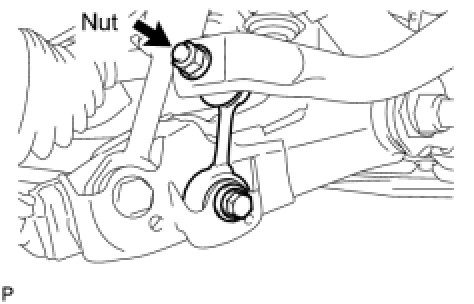
(a) Temporarily install the stabilizer link with the bolt.
(b) Temporarily install the stabilizer link with the nut.
(c) Tighten the nut.
Torque: 128 Nm (1305 kgf-cm, 94 ft-lbf)
12. TIGHTEN FRONT NO. 1 STABILIZER BRACKET LH
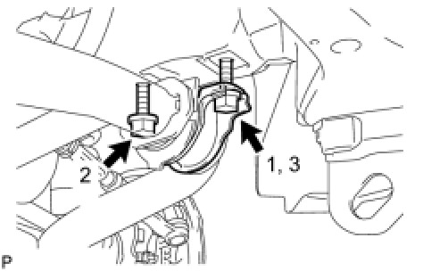
(a) Tighten the 2 bolts of the front stabilizer brackets.
Torque: 87 Nm (887 kgf-cm, 64 ft-lbf)
HINT:
Tighten the bolts in 3 steps, in the order shown in the illustration.
13. TIGHTEN FRONT NO. 1 STABILIZER BRACKET RH
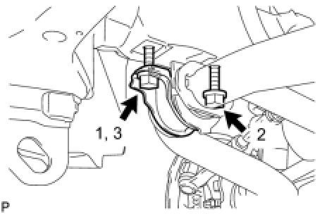
(a) Tighten the 2 bolts of the front stabilizer brackets.
Torque: 87 Nm (887 kgf-cm, 64 ft-lbf)
HINT:
Tighten the bolts in 3 steps, in the order shown in the illustration.
14. INSTALL NO. 1 ENGINE UNDER COVER SUB-ASSEMBLY Installation
15. INSTALL FRONT FENDER SPLASH SHIELD SUB-ASSEMBLY LH Installation
16. INSTALL FRONT FENDER SPLASH SHIELD SUB-ASSEMBLY RH Installation
17. STABILIZE SUSPENSION
(a) Install the front wheels.
Torque: 131 Nm (1336 kgf-cm, 97 ft-lbf)
(b) Lower the vehicle.
(c) Press down on the vehicle several times to stabilize the suspension.
18. TIGHTEN FRONT SHOCK ABSORBER WITH COIL SPRING
(a) Tighten the nut.
Torque: 180 Nm (1835 kgf-cm, 133 ft-lbf)
NOTICE:
Perform this procedure with all 4 wheels on the ground.
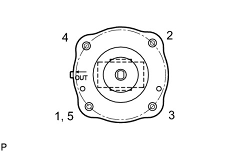
(b) Tighten the 4 upper nuts in diametrically opposite pairs.
Torque: 45 Nm (459 kgf-cm, 33 ft-lbf)
(c) Check that the first nut that was tightened is at the torque specification.
19. TIGHTEN FRONT STABILIZER LINK ASSEMBLY LH
(a) Tighten the bolt.
Torque: 135 Nm (1377 kgf-cm, 100 ft-lbf)
NOTICE:
Perform this procedure with all 4 wheels on the ground.
20. TIGHTEN FRONT STABILIZER LINK ASSEMBLY RH
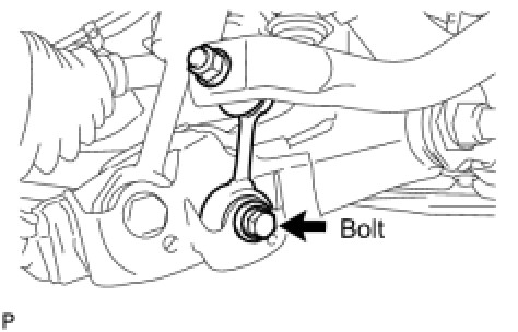
(a) Tighten the bolt.
Torque: 135 Nm (1377 kgf-cm, 100 ft-lbf)
NOTICE:
Perform this procedure with all 4 wheels on the ground.
21. PERFORM VEHICLE HEIGHT OFFSET CALIBRATION
(a) Perform the vehicle height offset calibration Testing and Inspection.