Part 1
INTERIOR PANELS / TRIM: ROOF HEADLINING: REMOVAL
1. OPEN BACK DOOR
(a) Open the back door before disconnecting the cable from the negative (-) battery terminal, as some procedures are performed with the back door open.
NOTICE:
The back door cannot be opened after the cable is disconnected from the negative (-) battery terminal.
2. REMOVE ENGINE ROOM SIDE COVER LH Removal
3. DISCONNECT CABLE FROM NEGATIVE BATTERY TERMINAL
CAUTION:
Wait at least 90 seconds after disconnecting the cable from the negative (-) battery terminal to disable the SRS system.
NOTICE:
- w/ Navigation System:
After the engine switch is turned off, the HDD navigation system requires approximately 6 minutes to record various types of memory and settings. As a result, after turning the engine switch off, wait 6 minutes or more before disconnecting the cable from the negative (-) battery terminal.
- When disconnecting the cable, some systems need to be initialized after the cable is reconnected Repair Instruction - Initialization.
4. REMOVE REAR NO. 2 SEAT ASSEMBLY LH
(a) w/ Manual Folding-up Function:
Remove the rear No. 2 seat assembly LH Removal.
(b) w/ Automatic Folding-up Function:
Remove the rear No. 2 seat assembly LH Removal.
5. REMOVE REAR NO. 2 SEAT ASSEMBLY RH
HINT:
Use the same procedures described for the LH side.
6. REMOVE FRONT DOOR SCUFF PLATE LH
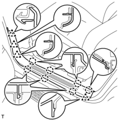
(a) w/o Illumination:
(1) Detach the 7 claws and 4 clips, and remove the scuff plate.
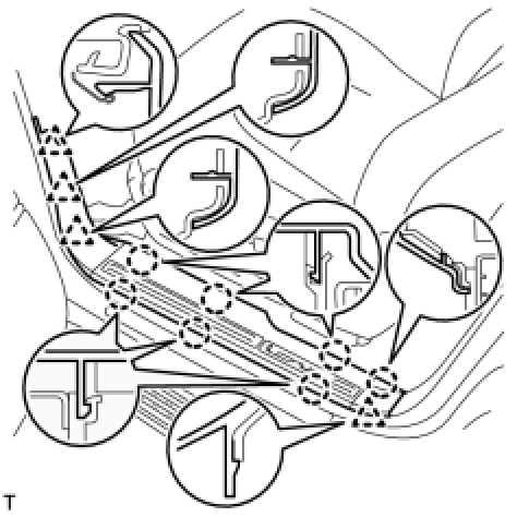
(b) w/ Illumination:
(1) Detach the 7 claws and 4 clips.
(2) Disconnect the connector and remove the scuff plate.
7. REMOVE FRONT DOOR SCUFF PLATE RH
HINT:
Use the same procedures described for the LH side.
8. REMOVE REAR STEP COVER
HINT:
Use the same procedure to remove the step cover on the other side.
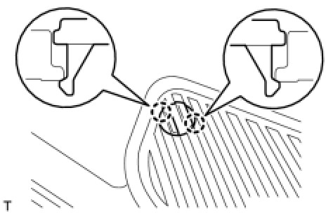
(a) w/o Illumination Type Front Door Scuff Plate:
Detach the 2 claws and remove the step cover.
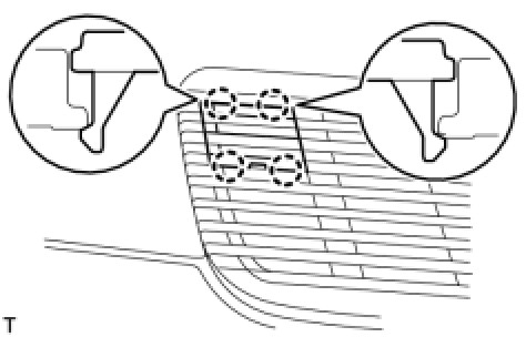
(b) w/ Illumination Type Front Door Scuff Plate:
Detach the 4 claws and remove the step cover.
9. REMOVE REAR DOOR SCUFF PLATE LH
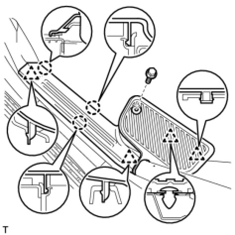
(a) w/o Illumination Type Front Door Scuff Plate:
Remove the rear door scuff plate.
(1) Remove the screw.
(2) Detach the 3 claws and 4 clips, and remove the scuff plate.
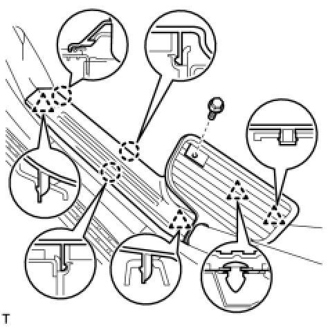
(b) w/ Illumination Type Front Door Scuff Plate:
Remove the rear door scuff plate.
(1) Remove the screw.
(2) Detach the 3 claws and 4 clips, and remove the scuff plate.
10. REMOVE REAR DOOR SCUFF PLATE RH
HINT:
Use the same procedures described for the LH side.
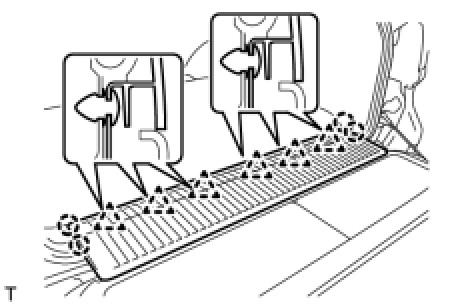
11. REMOVE REAR FLOOR MAT REAR SUPPORT PLATE
(a) Detach the 6 clips and 4 claws, and remove the support plate.
12. REMOVE FRONT ASSIST GRIP SUB-ASSEMBLY
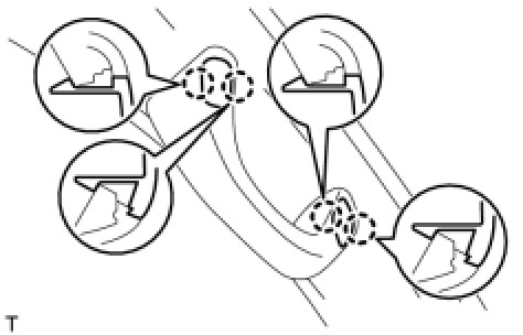
HINT:
Use the same procedure to remove the front assist grip on the other side.
(a) Detach the 4 claws and remove the 2 assist grip plugs.
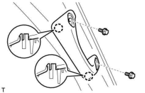
(b) Remove the 2 bolts.
(c) Detach the 2 claws and remove the front assist grip.
13. REMOVE FRONT PILLAR GARNISH LH
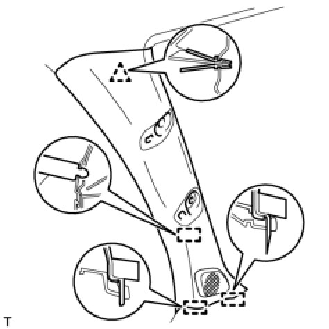
(a) Detach the clip and 3 guides.
(b) Disconnect the speaker connector and then remove the front pillar garnish.
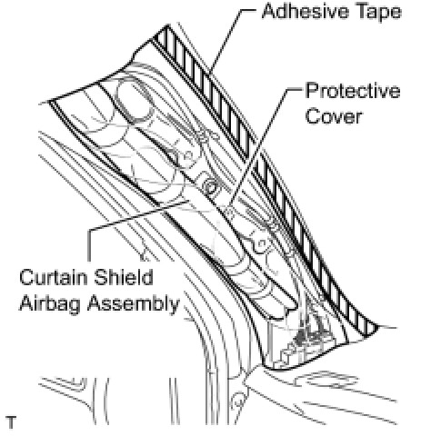
(c) Protect the curtain shield airbag.
(1) Thoroughly cover the airbag with a cloth or nylon sheet and fix the ends of the cover with adhesive tape, as shown in the illustration.
NOTICE:
Cover the curtain shield airbag with a protective cover as soon as the front pillar garnish is removed.
14. REMOVE FRONT PILLAR GARNISH RH
HINT:
Use the same procedures described for the LH side.
15. REMOVE CENTER PILLAR GARNISH COVER LH
HINT:
- When removing the center pillar garnish cover, connect the cable to the negative (-) battery terminal and operate the power seat switch to move the front seat and seatback to the foremost upright position.
- After moving the front seat, disconnect the cable from the negative (-) battery terminal.
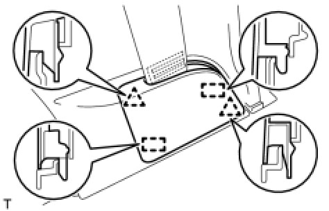
(a) Detach the 2 clips and 2 guides, and remove the cover.
16. REMOVE CENTER PILLAR GARNISH COVER RH
HINT:
Use the same procedures described for the LH side.
17. REMOVE CENTER LOWER PILLAR GARNISH LH
HINT:
- When removing the center lower pillar garnish, connect the cable to the negative (-) battery terminal and operate the power seat switch to move the front seat and seatback to the foremost upright position.
- After moving the front seat, disconnect the cable from the negative (-) battery terminal.
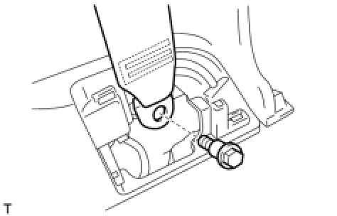
(a) Remove the bolt and seat belt anchor.
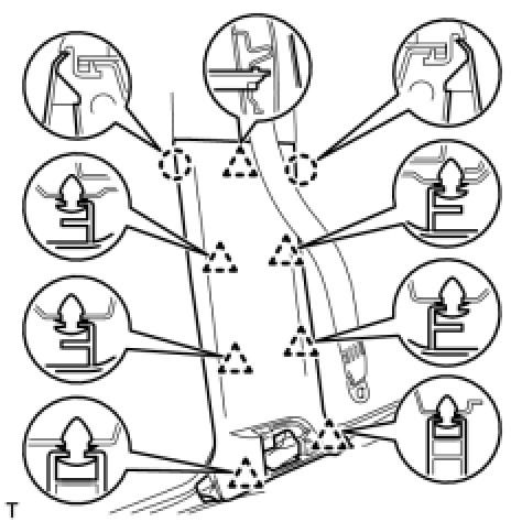
(b) Detach the 2 claws and 7 clips, and remove the center lower pillar garnish.
18. REMOVE CENTER LOWER PILLAR GARNISH RH
HINT:
- When removing the center lower pillar garnish, connect the cable to the negative (-) battery terminal and operate the power seat switch to move the front seat and seatback to the foremost upright position.
- After moving the front seat, disconnect the cable from the negative (-) battery terminal.
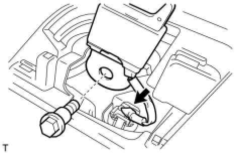
(a) Disconnect the connector.
(b) Remove the bolt and seat belt anchor.
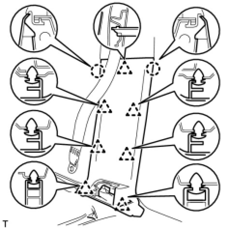
(c) Detach the 2 claws and 7 clips, and remove the center lower pillar garnish.
19. REMOVE REAR ASSIST GRIP ASSEMBLY
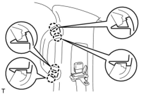
HINT:
Use the same procedure to remove the rear assist grip on the other side.
(a) Detach the 4 claws and remove the 2 assist grip plugs.
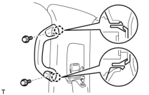
(b) Remove the 2 bolts.
(c) Detach the 2 claws and remove the rear assist grip.
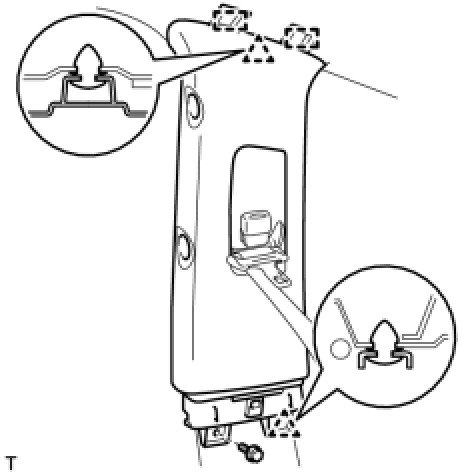
20. REMOVE CENTER PILLAR GARNISH LH
(a) Remove the bolt.
(b) Detach the 2 clips and 2 guides.
(c) Pass the seat belt anchor through the center pillar garnish, and remove the center pillar garnish.
21. REMOVE CENTER PILLAR GARNISH RH
HINT:
Use the same procedures described for the LH side.
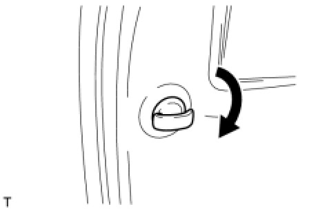
22. REMOVE NO. 1 LUGGAGE COMPARTMENT TRIM HOOK
HINT:
Use the same procedure to remove the luggage compartment trim hook on the other side.
(a) Remove the luggage compartment trim hook by turning it clockwise.
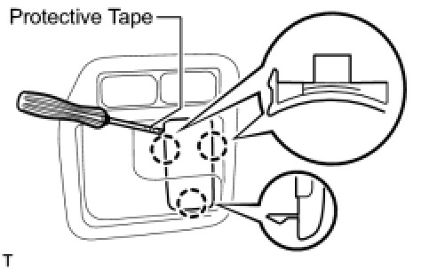
23. REMOVE REAR SEAT COVER CAP (for Rear No. 2 Seat with Manual Folding-up Function)
HINT:
Use the same procedure to remove the rear seat cover cap on the other side.
(a) Using a screwdriver, detach the 3 claws and remove the rear seat cover cap.
HINT:
Tape the screwdriver tip before use.
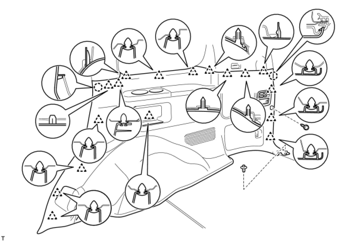
24. REMOVE FRONT QUARTER TRIM PANEL ASSEMBLY LH
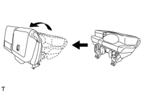
HINT:
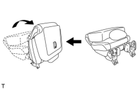
When removing the front quarter trim panel, operate the reclining adjuster release handle and move the No. 1 rear seat to the position shown in the illustration.
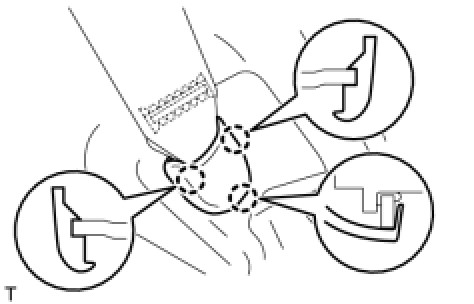
(a) Detach the 3 claws and remove the cover.
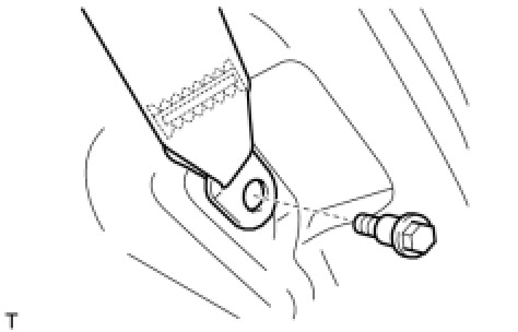
(b) Remove the bolt and rear No. 1 seat belt anchor.
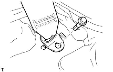
(c) Remove the bolt and rear No. 2 seat belt anchor.
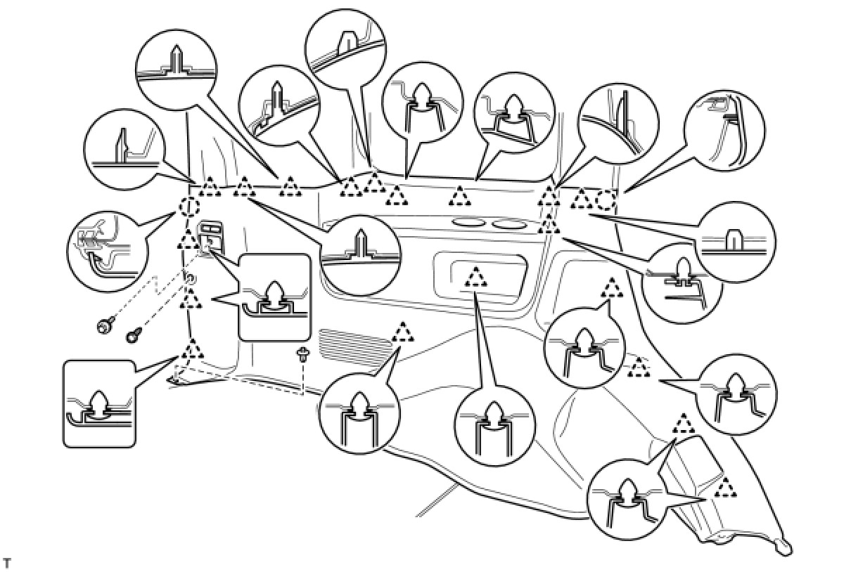
(d) for Rear No. 2 Seat with Manual Folding-up Function:
(1) Remove the screw, clip and bolt.
(2) Detach the 19 clips and 2 claws.
(3) Disconnect the thermistor connector, power outlet socket connector and rear seat lock control lever cable, and then remove the quarter trim panel.
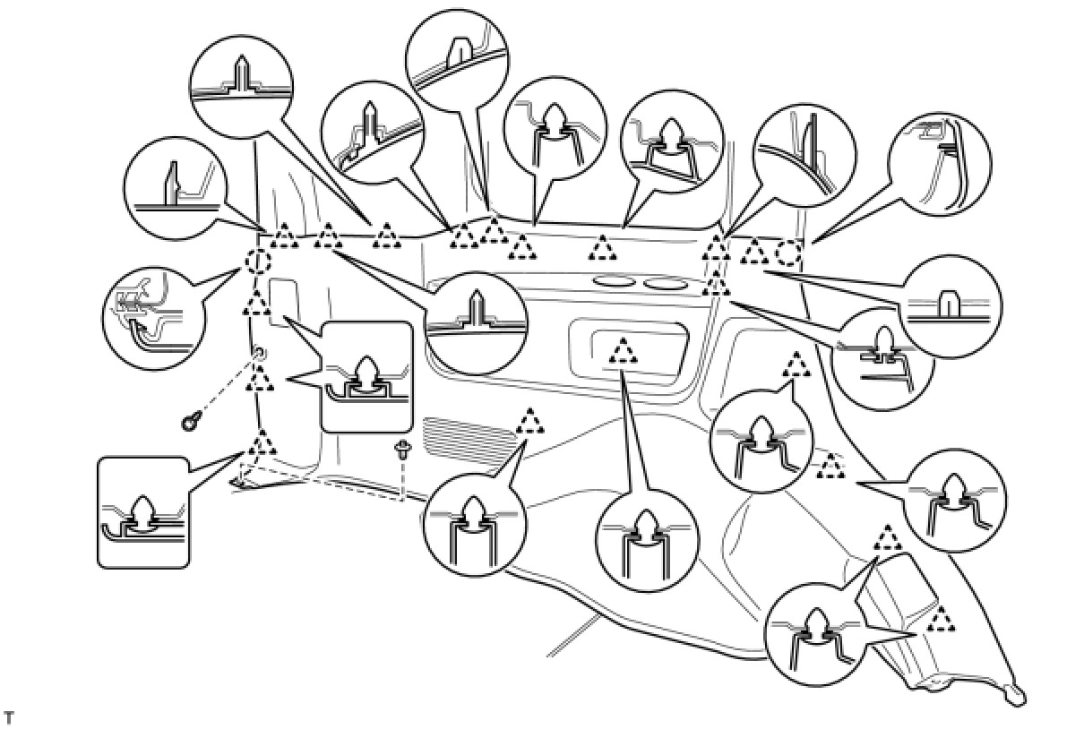
(e) for Rear No. 2 Seat with Automatic Folding-up Function:
(1) Remove the screw and clip.
(2) Detach the 19 clips and 2 claws.
(3) Disconnect the thermistor connector and power outlet socket connector, and then remove the quarter trim panel.
25. REMOVE FRONT QUARTER TRIM PANEL ASSEMBLY RH
HINT:
When removing the front quarter trim panel, operate the reclining adjuster release handle and move the No. 1 rear seat to the position shown in the illustration.
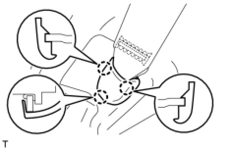
(a) Detach the 3 claws and remove the cover.
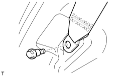
(b) Remove the bolt and rear No. 1 seat belt anchor.
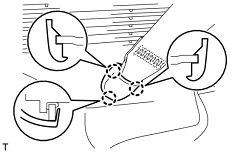
(c) Detach the 3 claws and remove the cover.
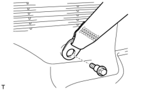
(d) Remove the bolt and rear No. 2 seat belt anchor.
(e) for Rear No. 2 Seat with Manual Folding-up Function:
(1) Remove the screw, clip and bolt.
(2) Detach the 17 clips and 2 claws.
(3) Disconnect the thermistor connector and rear seat lock control lever cable, and then remove the quarter trim panel.
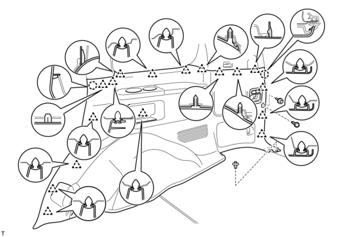
(f) for Rear No. 2 Seat with Automatic Folding-up Function:
(1) Remove the screw and clip.
(2) Detach the 17 clips and 2 claws.
(3) Disconnect the thermistor connector and then remove the quarter trim panel.
26. REMOVE REAR FRONT QUARTER TRIM GARNISH LH
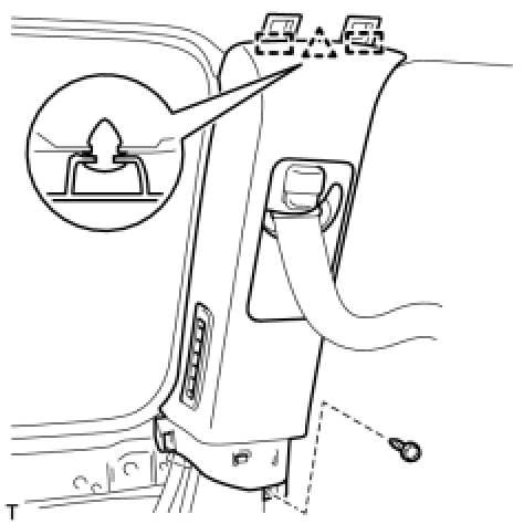
(a) Remove the screw.
(b) Detach the clip and 2 guides.
(c) Pass the seat belt anchor through the quarter trim garnish, and remove the quarter trim garnish.
27. REMOVE REAR FRONT QUARTER TRIM GARNISH RH
HINT:
Use the same procedures described for the LH side.
28. REMOVE REAR UPPER PILLAR GARNISH LH
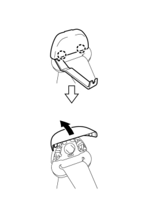
(a) Using a moulding remover, detach the 2 claws and open the seat belt shoulder anchor cover.
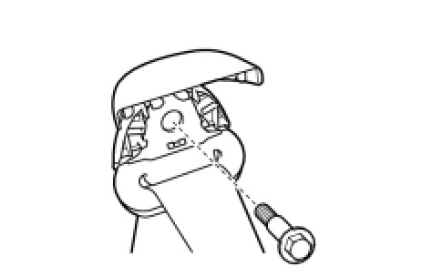
(b) Remove the bolt and seat belt shoulder anchor.
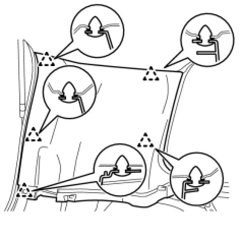
(c) Detach the 5 clips and remove the rear upper pillar garnish.
29. REMOVE CENTER BACK DOOR GARNISH (w/ Power Back Door) Disassembly
30. REMOVE BACK DOOR SIDE GARNISH RH (w/ Power Back Door) Disassembly
31. REMOVE BACK DOOR SERVICE HOLE COVER RH (w/ Power Back Door) Disassembly
32. REMOVE REAR UPPER PILLAR GARNISH RH
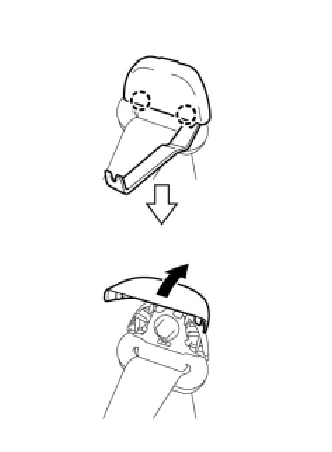
(a) Using a moulding remover, detach the 2 claws and open the seat belt shoulder anchor cover.
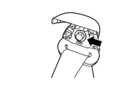
(b) Remove the bolt and seat belt shoulder anchor.
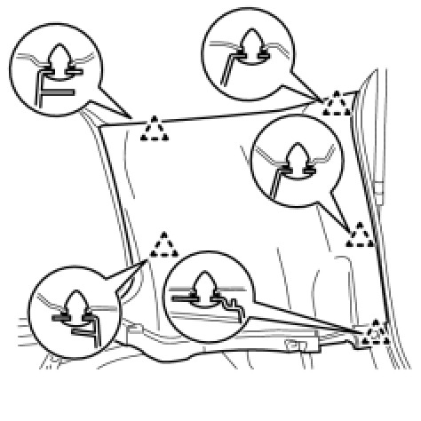
(c) w/o Power Back Door:
(1) Detach the 5 clips and remove the rear upper pillar garnish.
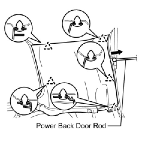
(d) w/ Power Back Door:
(1) Detach the 5 clips.
(2) Pass the power back door rod through the rear upper pillar garnish, and remove the rear upper pillar garnish.
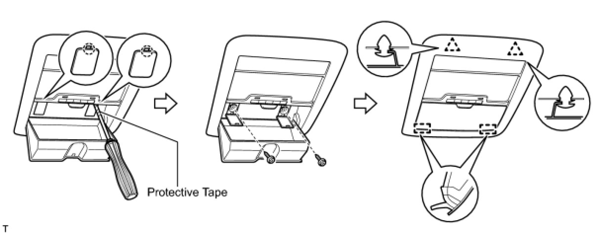
33. REMOVE MAP LIGHT ASSEMBLY
(a) Using a screwdriver, detach the 2 claws and open the 2 covers.
HINT:
Tape the screwdriver tip before use.
(b) Remove the 2 screws.
(c) Detach the 2 clips and 2 guides.
(d) Disconnect the 2 connectors and then remove the map light.
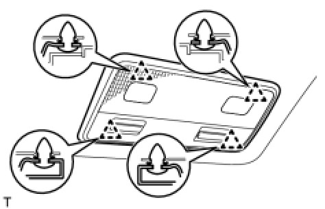
34. REMOVE NO. 1 ROOM LIGHT ASSEMBLY (w/o Rear Seat Entertainment System)
(a) Detach the 4 clips.
(b) Disconnect the connector and then remove the room light.
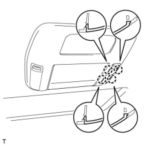
35. REMOVE NO. 1 ROOF LINING TRIM COVER (w/ Rear Seat Entertainment System)
(a) Detach the 4 claws and remove the cover.
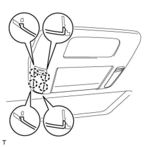
36. REMOVE NO. 2 ROOF LINING TRIM COVER (w/ Rear Seat Entertainment System)
(a) Detach the 4 claws and remove the cover.
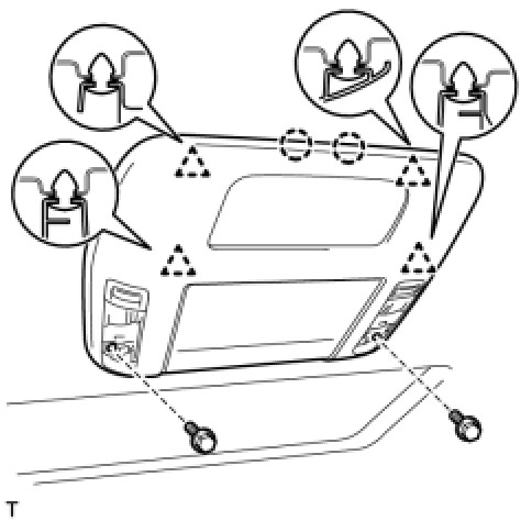
37. REMOVE ROOF CONSOLE BOX ASSEMBLY (w/ Rear Seat Entertainment System)
(a) Remove the 2 bolts.
(b) Detach the 4 clips and 2 claws.
(c) Disconnect the connector and then remove the roof console box.
38. REMOVE NO. 3 ROOM LIGHT ASSEMBLY
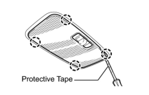
(a) Using a screwdriver, detach the 4 claws and remove the room light lens.
HINT:
Tape the screwdriver tip before use.
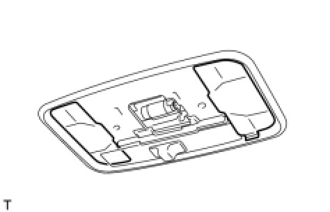
(b) Remove the 2 covers.
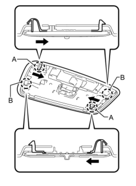
(c) Using a screwdriver, push the 2 levers in the direction of the arrows in the illustration, and detach the 2 claws labeled A.
(d) Detach the 2 claws labeled B.
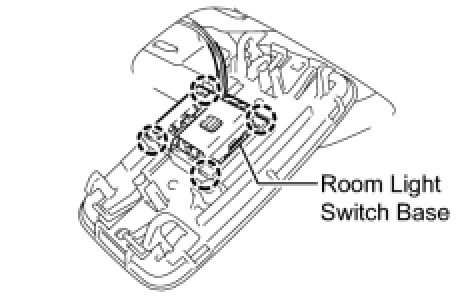
(e) Detach the 4 claws and remove the room light from the room light switch base.
39. REMOVE VISOR BRACKET COVER
HINT:
Use the same procedure to remove the visor bracket cover on the other side.
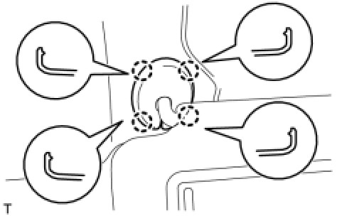
(a) Detach the 4 claws and remove the visor bracket cover.
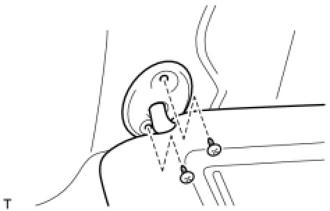
40. REMOVE VISOR ASSEMBLY LH
(a) Remove the 2 screws and visor.
41. REMOVE VISOR ASSEMBLY RH
HINT:
Use the same procedures described for the LH side.
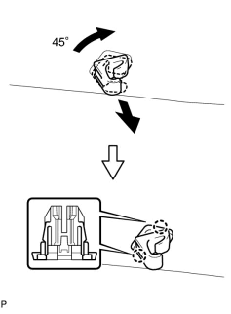
42. REMOVE VISOR HOLDER
HINT:
Use the same procedure to remove the visor holder on the other side.
(a) Turn the visor holder approximately 45° and pull it out as shown in the illustration.
(b) Detach the 2 claws and remove the visor holder.
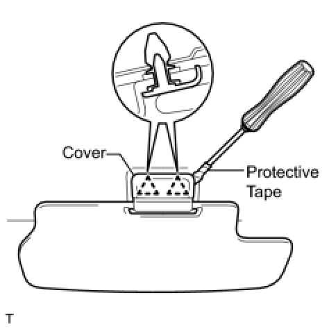
43. REMOVE CENTER VISOR ASSEMBLY LH
(a) Using a screwdriver, pry off the cover to detach the 2 clips and remove the center visor.
HINT:
Tape the screwdriver tip before use.
44. REMOVE CENTER VISOR ASSEMBLY RH
HINT:
Use the same procedures described for the LH side.
45. REMOVE INNER REAR VIEW MIRROR STAY HOLDER COVER Removal