- For conventional (not LSD) differential, go to step 6. For LSD models, lubricate discs and plates with limited slip differential oil. Position specified number of discs and plates on rear of side gear. Always position a friction plate first on rear of side gear. On H190A models, install spring disc and spring plate. See Fig 1. Install side gear thrust washer into differential case "A".
- On H223B models, install spring plate. See Fig 2 or Fig 3. Ensure friction plates are aligned. Install friction plate guides. Apply grease to inner surfaces of friction plate guides to hold them in position. Install differential case "B" over assembly while supporting friction plate guides with your middle finger inserted through oil hole in differential case.
- On H190A models, install differential case "A" over side gear assembly. Install pinion mate gears, pinion shaft and thrust block into differential case "A". On H233B models, install pinion mate gears and thrust washers on pinion mate shaft. Install pinion mate shaft in differential case "B". On all models, install side gear to pinion mate gears. Install friction discs and plates to side gear using same procedure as used in steps 1) and 2).
- On H190A models, install side gear thrust washer to differential case "B". On all models, align mating marks, and install remaining differential case. Tighten bolts in a crisscross pattern to specification. See TORQUE SPECIFICATIONS . On H190A models, check clearance between differential cases. If any clearance exists, use thinner thrust washers on both sides. Bend lock strap tabs up.
- On all models, check LSD rotating torque. See step 8) under DISASSEMBLY. If LSD rotating torque is greater than specification, use thinner friction discs. If LSD rotating torque is less than specification, use thicker friction discs. If LSD rotating torque is okay, go to step 8.
- Install side gears, thrust washers and pinion mate gears in differential case. Install pinion mate shaft. Adjust backlash between side gear and pinion mate gear by adjusting clearance between side gear thrust washer and differential case. Select side gear thrust washer to obtain specified clearance. On H190A models, clearance should be less than 0.006" (0.15 mm). On H233B models, clearance should be 0.004-0.008" (0.10-0.20 mm).
- On all models, install selected thrust washers, side gears and pinion shaft in differential case. Install pinion mate shaft lock pin using a punch. Ensure lock pin is flush with case. Apply gear oil to gears and contact surfaces. Ensure gears rotate smoothly.
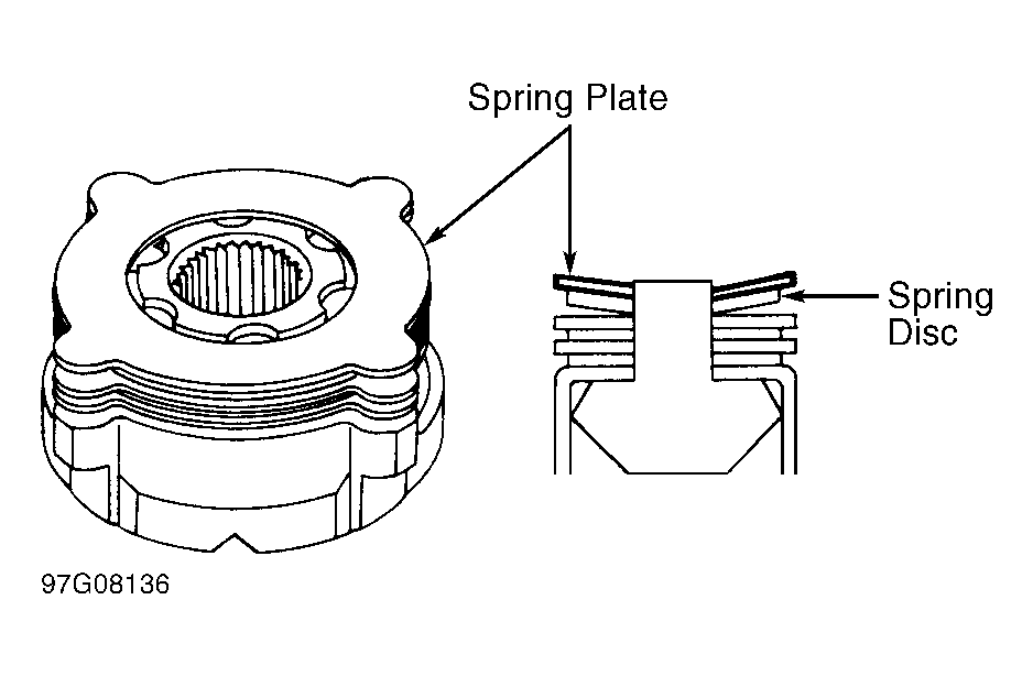 Courtesy of NISSAN MOTOR CO., U.S.A.
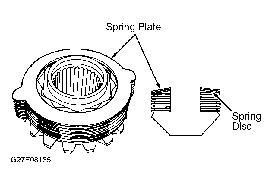 Courtesy of NISSAN MOTOR CO., U.S.A.
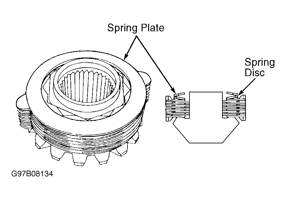 Courtesy of NISSAN MOTOR CO., U.S.A.
- Install ring gear on differential case. Apply Loctite to ring gear retaining bolt threads. Install new lock strap (if equipped) and loosely install ring gear bolts.
- Tighten ring gear bolts gradually in a crisscross pattern to specification while lightly tapping bolt heads using a hammer. See TORQUE SPECIFICATIONS . Bend lock strap ends up (if equipped). On H233B, press side bearings on differential case (if not already installed). Ensure bearings are installed in original locations.
- For H233B, go to step 14. For H190A, install original side bearing adjusting shims on differential case. Press side bearings on differential case. Ensure bearings are installed in their original locations. Lubricate side bearings with ATF. Install races on side bearings.
- Install differential case assembly and bearing races in axle housing. Loosely install side bearing caps in original locations.
- Rotate ring gear to seat bearings. Using a spring scale, measure differential rotating torque at ring gear retaining bolt. Rotating torque should be 7.7-8.8 lbs. (3.5-4.0 kg).
- Increase adjusting shim thickness if turning torque is less than specification. Decrease shim thickness if turning torque exceeds specification. Record shim thickness required. Remove side bearing caps and differential case assembly from axle housing, and install selected shims on differential case.
- On all models, press side bearing inner races on differential case. Press front and rear drive pinion bearing outer races into differential housing. Assemble drive pinion gear bearings onto Differential Shim Selector (J-34309).
- On front pinion bearing, ensure that Seat (J-34309-3) is securely tightened to Gauge Anvil (J-34309-2). Turn front pinion bearing Pilot (J-34309-5) to secure bearing in its proper position.
- On rear pinion bearing, rear pinion bearing Pilot (J-34309-8) is used to center rear pinion bearing only. Rear Pinion Bearing Locking Seat (J-34309-4) is used to lock bearing onto shim selector assembly.
- Place Pinion Bearing Preload Shim Selector Screw (J-34309-1), with pinion rear bearing cone installed, into differential housing. Install gauge anvil with front pinion bearing into case, and attach to screw.
- Attach Gauge Plate (J-34309-16) to shim selector assembly. Ensure gauge plate turns a full 360 degrees. Tighten sections by hand. Turn washer selector assembly several times to seat bearings.
- Measure pinion bearing turning torque at end of washer selector shaft. Turning torque should be 8.7-11.3 INCH lbs. (1.0-1.3 N.m) for H190A, and 3.5-7.8 INCH lbs. (.4-.9 N.m) for H233B.
- Place appropriate Pinion Height Adapter onto gauge plate and tighten it by hand. See PINION HEIGHT ADAPTER SPECIFICATION table. Ensure all machined surfaces are clean.
PINION HEIGHT ADAPTER SPECIFICATION
| Application |
Adapter No. |
| H190A |
J-34309-14 |
| H233B |
J-34309-12 |
- Place Side Bearing Discs (J-25269-18) and arbor into side bearing bores. Install side bearing caps and tighten bolts to specification. See TORQUE SPECIFICATIONS .
- Select correct pinion height adjustment washer thickness. Use a standard gauge if necessary. Measure gap between pinion height adapter and arbor. Write down exact total measurement.
- Determine size of pinion height adjustment washer by referring to pinion head number stamped on pinion gear. See Fig 4. There are 2 numbers on pinion gear. Larger number should match number on ring gear. Smaller number is pinion head height number, and shows deviation from pinion height standard. Smaller number may be preceded by plus (+) or minus (-) sign.
- Use PINION HEIGHT ADJUSTMENT COMPENSATION table to determine correct size of pinion height adjustment washer. Select pinion height adjustment washer from appropriate PINION HEIGHT ADJUSTMENT WASHERS table. Remove side bearing caps, differential case assembly, and washer selector assembly from axle housing. Install selected washers.
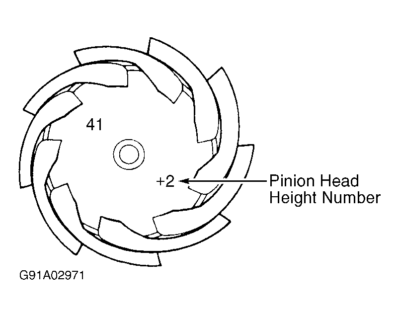 Courtesy of NISSAN MOTOR CO., U.S.A.
 PINION HEIGHT ADJUSTMENT COMPENSATION
| Number Stamped On Pinion Head |
Compensate Thickness - In. (mm) |
| -6 |
Add .0024 (.060) |
| -5 |
Add .0020 (.050) |
| -4 |
Add .0016 (.040) |
| -3 |
Add .0012 (.030) |
| -2 |
Add .0008 (.020) |
| -1 |
Add .0004 (.010) |
| 0 |
Use Selected Washer |
| +1 |
Subtract .0004 (.010) |
| +2 |
Subtract .0008 (.020) |
| +3 |
Subtract .0012 (.030) |
| +4 |
Subtract .0016 (.040) |
| +5 |
Subtract .0020 (.050) |
| +6 |
Subtract .0024 (.060) |
PINION HEIGHT ADJUSTMENT WASHERS (H190A)
| Thickness - In. (mm) |
Part No. |
| .1016 (2.581) |
38154-P6000 |
| .1028 (2.611) |
38154-P6001 |
| .1039 (2.639) |
38154-P6002 |
| .1051 (2.670) |
38154-P6003 |
| .1063 (2.700) |
38154-P6004 |
| .1075 (2.731) |
38154-P6005 |
| .1087 (2.761) |
38154-P6006 |
| .1098 (2.789) |
38154-P6007 |
| .1110 (2.819) |
38154-P6008 |
| .1122 (2.850) |
38154-P6009 |
| .1134 (2.880) |
38154-P6010 |
| .1146 (2.911) |
38154-P6011 |
| .1157 (2.939) |
38154-P6012 |
| .1169 (2.969) |
38154-P6013 |
| .1181 (3.000) |
38154-P6014 |
| .1193 (3.030) |
38154-P6015 |
| .1205 (3.061) |
38154-P6016 |
| .1217 (3.091) |
38154-P6017 |
| .1228 (3.119) |
38154-P6018 |
| .1240 (3.150) |
38154-P6019 |
| .1252 (3.180) |
38154-P6020 |
PINION HEIGHT ADJUSTMENT WASHERS (H233B)
| Thickness - In. (mm) |
Part No. |
| .1016 (2.581) |
38151-01J00 |
| .1028 (2.611) |
38151-01J01 |
| .1039 (2.639) |
38151-01J02 |
| .1051 (2.670) |
38151-01J03 |
| .1063 (2.700) |
38151-01J04 |
| .1075 (2.731) |
38151-01J05 |
| .1087 (2.761) |
38151-01J06 |
| .1098 (2.789) |
38151-01J07 |
| .1110 (2.819) |
38151-01J08 |
| .1122 (2.850) |
38151-01J09 |
| .1134 (2.880) |
38151-01J10 |
| .1146 (2.911) |
38151-01J11 |
| .1157 (2.939) |
38151-01J12 |
| .1169 (2.969) |
38151-01J13 |
| .1181 (3.000) |
38151-01J14 |
| .1193 (3.030) |
38151-01J15 |
| .1205 (3.061) |
38151-01J16 |
| .1217 (3.091) |
38151-01J17 |
| .1228 (3.119) |
38151-01J18 |
| .1240 (3.150) |
38151-01J19 |
| .1252 (3.180) |
38151-01J60 |
| .1264 (3.211) |
38151-01J61 |
| .1276 (3.241) |
38151-01J62 |
| .1287 (3.269) |
38151-01J63 |
| .1299 (3.299) |
38151-01J64 |
| .1311 (3.330) |
38151-01J65 |
| .1323 (3.360) |
38151-01J66 |
| .1335 (3.391) |
38151-01J67 |
| .1346 (3.419) |
38151-01J68 |
| .1358 (3.449) |
38151-01J69 |
| .1370 (3.480) |
38151-01J70 |
| .1382 (3.510) |
38151-01J71 |
| .1394 (3.541) |
38151-01J72 |
| .1406 (3.571) |
38151-01J73 |
| .1417 (3.599) |
38151-01J74 |
| .1429 (3.630) |
38151-01J75 |
| .1441 (3.660) |
38151-01J76 |
- Install drive pinion height adjustment washer on drive pinion. Press bearing race onto drive pinion. Install pinion front bearing differential housing. On H190A models, lubricate front oil seal with grease, and install on case. Install ABS sensor (if equipped).
- On all models, assemble drive pinion and components into differential case. See Figure, Figure or Figure. Tap pinion (companion) flange onto drive pinion. Clean oil and grease from threaded portion of drive pinion.
NOTE:
On H190A, if maximum preload is attained before reaching minimum pinion nut torque or if minimum preload is not reached before pinion nut is tightened to maximum torque, replace collapsible spacer and repeat preload procedure. See TORQUE SPECIFICATIONS .
- For H233B, go to step 33). On H190A, temporarily tighten pinion nut until no axial play exists. Tighten drive pinion nut by very small degrees until pinion preload is 9.5-13.9 INCH lbs. (1.1-1.6 N.m). Turn drive pinion in both directions several times to seat bearings before checking preload each time.
- Install differential case into carrier. Install side bearing preload adjustment washers, spacer and side bearing retainer. Install side bearing caps in original locations, and tighten to specification. See TORQUE SPECIFICATIONS .
- Measure ring gear-to-drive pinion backlash. See Figure. Backlash should be .005-.007" (.13-.18 mm). If backlash is too small, decrease thickness of left washer and increase thickness of right washer by same amount. If backlash is too large, reverse procedure.
NOTE:
When adjusting total pinion bearing preload, always add or remove same amount of washers to or from each side. If amount of washers varies from side to side, ring gear-to-drive pinion backlash will change.
- Turn drive pinion flange in both directions to seat bearings. Check total pinion bearing preload. Total pinion bearing preload should be 10-19 INCH lbs. (1.1-2.2 N.m). See Figure. If preload is too small, add same amount of washers to each side. If preload is too large, remove same amount of washers from each side.
- Recheck ring gear-to-drive pinion backlash. If backlash is correct, check ring gear runout. Ring gear runout must not exceed .002"(.05 mm). If backlash varies excessively, foreign matter may be caught between ring gear and differential case.
- If backlash varies greatly when runout of ring gear is within specification, hypoid gear set or differential case should be replaced. Check gear tooth contact pattern and adjust (if necessary). See GEAR TOOTH CONTACT PATTERNS
article in GENERAL INFORMATION.
- On H233B, tighten drive pinion nut to specification. See TORQUE SPECIFICATIONS . Turn drive pinion in both directions several times to seat bearings. Measure pinion bearing preload.
- Bearing preload (without front oil seal) should be 10-14 INCH lbs. (1.1-1.6 N.m) on H190A, 11-13 INCH lbs. (1.2-1.5 N.m) on H233B (4-pinion type differential), or 12-15 INCH lbs. (1.4-1.7 N.m) on H233B (2-pinion type differential). If pinion bearing preload (without front oil seal) is not as specified, adjust thickness of shim and spacer combination. If pinion bearing preload is okay, lubricate and install front oil seal.
- Install differential case into carrier. Install side bearing adjusters until threads are engaged. DO NOT tighten side bearing adjusters. Install side bearing caps in their original locations, and loosely install side bearing cap bolts.
NOTE:
Rotate drive pinion several times before checking preload each time.
- Slowly tighten side bearing adjusters while measuring ring gear backlash and total pinion preload. Alternately tighten right and left side bearing adjusters to obtain correct ring gear backlash and total pinion preload. See INSPECTION SPECIFICATIONS table.
- When ring gear backlash and total pinion preload are adjusted properly, tighten side bearing cap bolts to specification. See TORQUE SPECIFICATIONS . Ring gear runout must not exceed .003" (.08 mm). If backlash varies excessively, foreign matter may be caught between ring gear and differential case.
- If backlash varies greatly when runout of ring gear is within specification, hypoid gear set or differential case should be replaced. Check gear tooth contact pattern and adjust (if necessary). See GEAR TOOTH CONTACT PATTERNS
article in GENERAL INFORMATION.