- Release fuel pressure. See FUEL PRESSURE RELEASE
under REMOVAL & INSTALLATION. Drain cooling system and cylinder block. Disconnect necessary coolant hoses, fuel hoses, vacuum hoses, control cables and electrical connections.
- Remove air duct to intake manifold, radiator, drive belts and water pump pulley. Remove alternator, power steering pump and spark plugs. Remove lower engine cover.
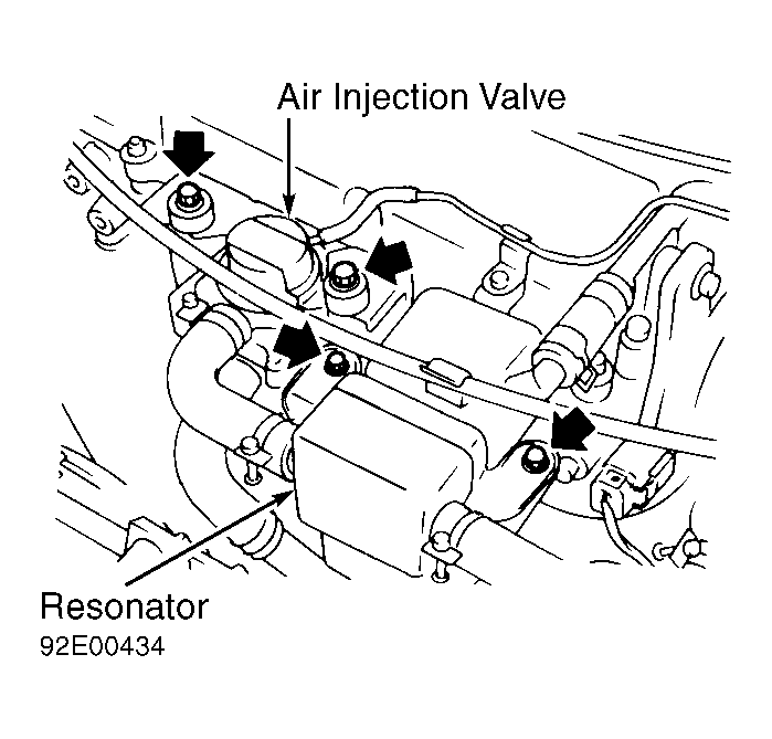
- Remove air injection valve and resonator. See Fig 1
. Remove valve cover nuts in proper sequence. See Fig 2
. Remove valve cover, gasket and oil separator.
 Courtesy of NISSAN MOTOR CO., U.S.A.
 Courtesy of NISSAN MOTOR CO., U.S.A.
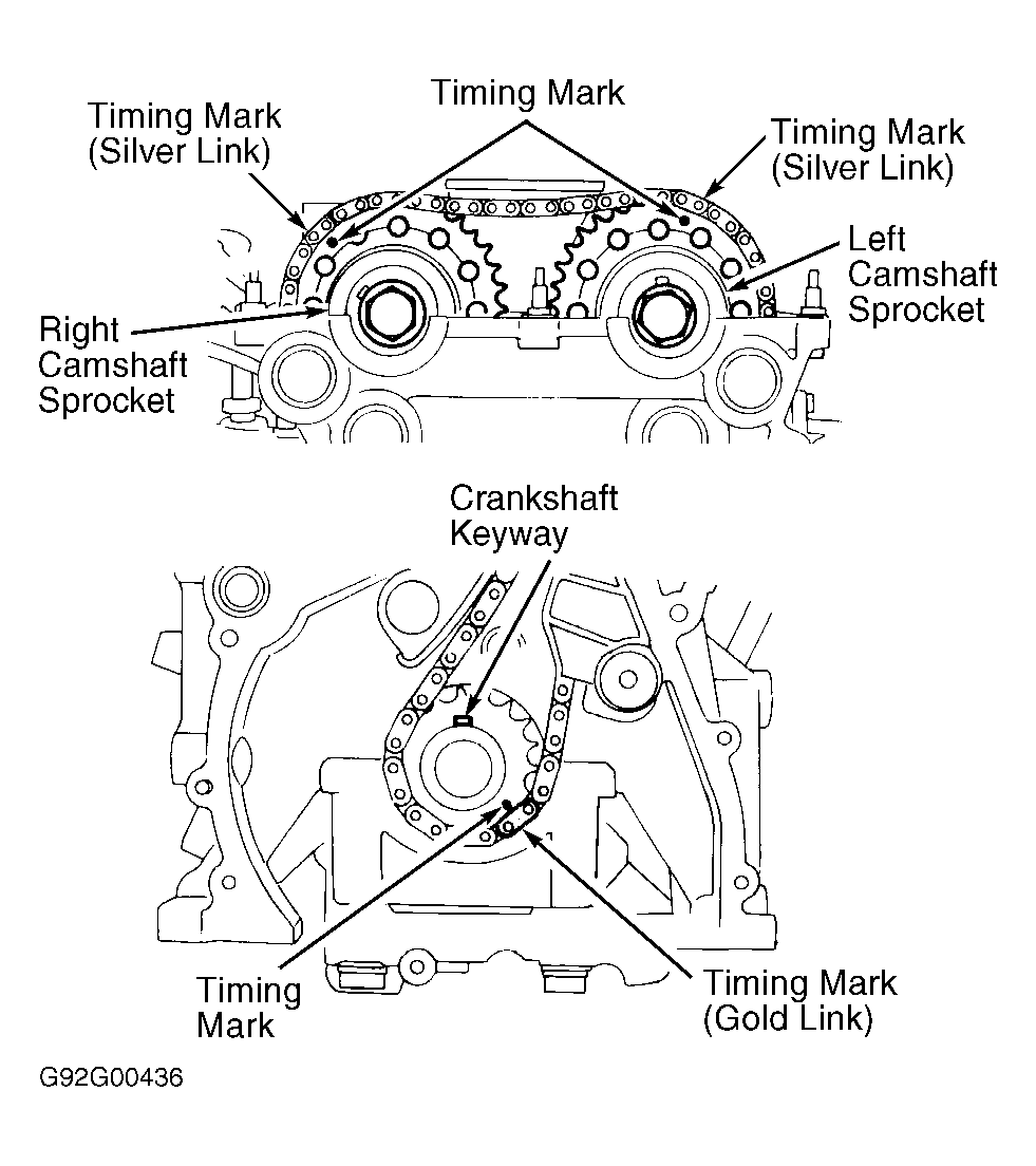
- Remove intake manifold support braces. Remove oil filter bracket and power steering pump bracket. Rotate crankshaft until No. 1 cylinder is at TDC of compression stroke and timing marks on camshaft sprockets are properly positioned. See Fig 3
. Ensure timing mark pointer on front cover aligns with "0" mark on crankshaft pulley.
 Courtesy of NISSAN MOTOR CO., U.S.A.
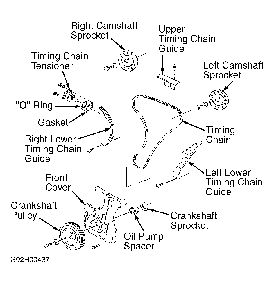
- Note direction of arrow on timing chain tensioner, located on right side of cylinder head. Remove timing chain tensioner, "0" ring and gasket from cylinder head. See Fig 4
. Remove distributor cap. Remove distributor. Remove upper timing chain guide.
 Courtesy of NISSAN MOTOR CO., U.S.A.
- Remove camshaft sprocket retaining bolts while holding camshaft using wrench installed on area located behind camshaft sprocket. Remove camshaft sprockets with timing chain.
CAUTION:
DO NOT rotate crankshaft or camshafts with timing chain removed or engine damage may result.
- Remove camshaft bearing cap bolts in sequence. See Fig 5
. Note bolt location for reassembly reference.
CAUTION:
Note direction and location of camshaft bearing cap installation. Camshaft bearing caps contain an arrow which points toward timing chain side of engine. No. 1-4 camshaft bearing caps are numbered for location with No. 1 at timing chain side. Rear (end) camshaft bearing caps are not numbered.
 Courtesy of NISSAN MOTOR CO., U.S.A.
- Remove oil tubes, baffle plate, camshaft bearing caps and camshafts. Disconnect necessary coolant hoses and brackets from cylinder head and front cover. Remove starter. Remove outside cylinder head bolts.
CAUTION:
Outside cylinder head bolts are located at front cover and near distributor.
- Using Cylinder Head Bolt Wrench (J-24239-01), loosen cylinder head-to-cylinder block bolts in 3 steps and in sequence. See Fig 6
. Remove cylinder head with intake and exhaust manifold attached.
 Courtesy of NISSAN MOTOR CO., U.S.A.
- Remove oil pan. See OIL PAN
under REMOVAL & INSTALLATION. Remove oil pump pick-up tube and baffle plate. Remove crankshaft pulley retaining bolt. Using puller, remove crankshaft pulley.
- Support engine using floor jack positioned under main bearing caps. Remove engine mount located on front cover. Remove retaining bolts and front cover. Remove lower timing chain guides and timing chain. Remove oil pump spacer and crankshaft sprocket (if necessary). See Fig 4
.