- Do the 12 volt battery terminal disconnection procedure (see
12 VOLT BATTERY TERMINAL DISCONNECTION AND RECONNECTION
).
- Raise and support the vehicle (see
LIFT AND SUPPORT POINTS
).
- Remove the front wheels.
- Release the lock lever, and adjust the steering column to the full tilt down position, and to the full telescopic in position.
- Tighten the lock lever.
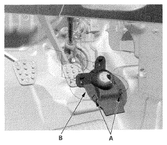
- Release the hooks (A), then remove the steering joint cover (B).
 Courtesy of AMERICAN HONDA MOTOR CO., INC.
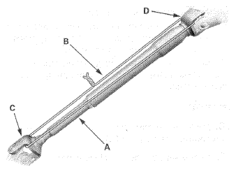
- Hold the splined shaft (A) on the column with a piece of wire (B) between the joint yoke (C) of the splined shaft and joint yoke (D) of the splined tube to prevent the splined shaft from pulling out.
 Courtesy of AMERICAN HONDA MOTOR CO., INC.
- Release the lock lever, and adjust the steering column to the full telescopic out position, then tighten the lock lever.
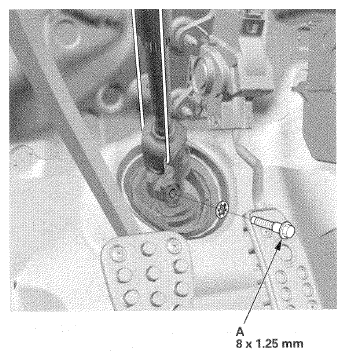
- Remove the steering joint bolt (A).
 Courtesy of AMERICAN HONDA MOTOR CO., INC.
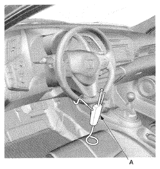
- Center the steering wheel spokes, and install a commercially available steering wheel holder tool (A).
 Courtesy of AMERICAN HONDA MOTOR CO., INC.
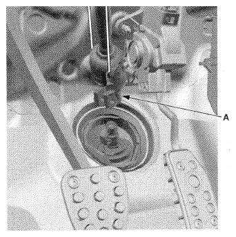
- Disconnect the steering joint (A) by moving the steering joint toward the column.
 Courtesy of AMERICAN HONDA MOTOR CO., INC.
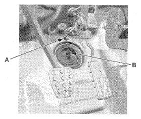
- Remove the center guide (A) (if equipped) from the top of the pinion shaft (B), and discard it.
NOTE:
The center guide is for factory assembly use only.
 Courtesy of AMERICAN HONDA MOTOR CO., INC.
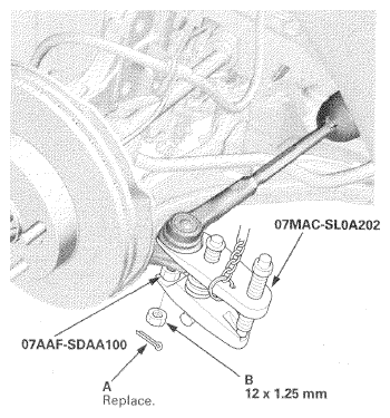
- Remove the cotter pin (A) from the tie-rod end ball joint, then remove the nut (B) on both sides.
 Courtesy of AMERICAN HONDA MOTOR CO., INC.
- Disconnect the tie-rod end ball joint from the knuckle using the ball joint remover and the ball joint thread protector (see
BALL JOINT REMOVAL
) on both sides.
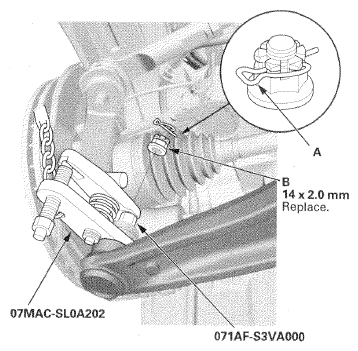
- Remove the lock pin (A) from the lower arm ball joint, and remove the castle nut (B) from both sides.
 Courtesy of AMERICAN HONDA MOTOR CO., INC.
- Disconnect the lower arm ball joint from the knuckle using the ball joint remover and the ball joint thread protector (see
BALL JOINT REMOVAL
) on both sides.
- Remove the stabilizer links from the stabilizer bar (see
STABILIZER LINK REMOVAL/INSTALLATION
) on both sides.
- Remove the splash shield (see
SPLASH SHIELD REPLACEMENT
).
- Disconnect the EPS motor 3P connector (A) by pushing the lock (B) and pulling up the lever (C), then disconnect the torque sensor 6P connector (D) and the EPS motor angle sensor 8P connector (E) from the steering gearbox.
NOTE:
Wrap the connectors with vinyl tape to avoid contamination from grease or water.
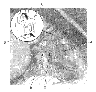 Courtesy of AMERICAN HONDA MOTOR CO., INC.
- Remove the secondary HO2S wire (A) from the clamp (B).
NOTE:
Do not disconnect the secondary HO2S 4P connector and the secondary HO2S.
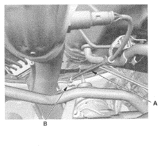 Courtesy of AMERICAN HONDA MOTOR CO., INC.
- Place a jack (A) under the middle of the IMA motor housing.
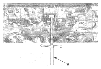 Courtesy of AMERICAN HONDA MOTOR CO., INC.
- Remove the torque rod (A).
NOTE:
Make sure the tab (B) on the bolt head aligned with the guide (C) on the front subframe.
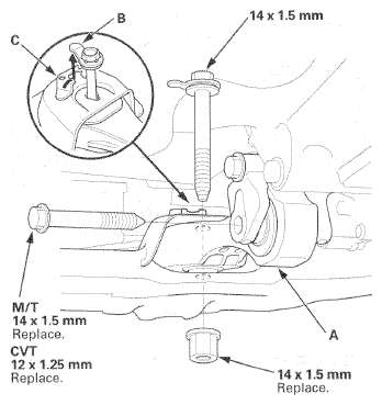 Courtesy of AMERICAN HONDA MOTOR CO., INC.
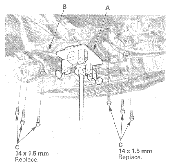
- Attach a transmission jack (A) to the middle of the front subframe (B), and support the front subframe securely by raising the transmission jack.
 Courtesy of AMERICAN HONDA MOTOR CO., INC.
- Remove the front subframe mounting bolts (C).
- Lower the front subframe and the steering gearbox as an assembly by lowering the jack slowly.
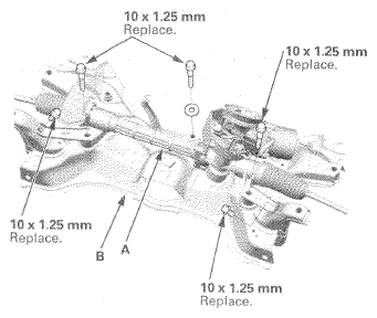
- Remove the steering gearbox (A) from the front subframe (B).
 Courtesy of AMERICAN HONDA MOTOR CO., INC.
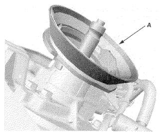
- Remove the pinion shaft grommet (A).
 Courtesy of AMERICAN HONDA MOTOR CO., INC.