Fluid Pump Selective Measurement
WARNING: This page is about a different car, the 2010 GMC Sierra, 2010 GMC Cab & Chassis Sierra, 2010 Chevrolet Silverado, and 2010 Chevrolet Cab & Chassis Silverado. However, it is still accessible from the selected car via links, so may be relevant.
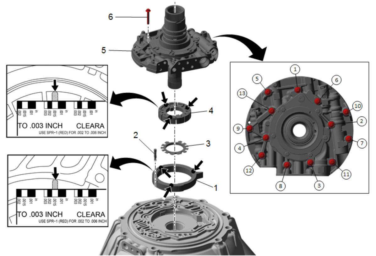 Courtesy of GENERAL MOTORS CORP.
| Callout |
Component Name |
|
Preliminary Procedures
- Clean and inspect all components and machined surfaces.
- After cleaning the transmission components, allow to air dry. Do not use cloth or paper towels in order to dry any transmission components.
|
| 1 |
Fluid Pump Slide Procedure
- Install an existing and/or undamaged pump slide.
- Place gauging plastic in three locations on the pump slide surface facing the pump cover, up.
|
| 2 |
Fluid Pump Slide Pivot Pin |
| 3 |
Fluid Pump Rotor Guide
Tip:
Align the rotor guide tabs to the notches on the bottom of the rotor. |
| 4 |
Fluid Pump Rotor Procedure
- Install an existing and/or undamaged pump rotor.
- Place gauging plastic in three locations on the pump rotor surface facing the pump cover, up.
|
| 5 |
Fluid Pump Cover Assembly |
| 6 |
Fluid Pump Cover Bolts M6 x 40 (Qty: 13)
Procedure
- Hand tighten the bolts.
- Tighten the fluid pump cover bolts in the sequence shown.
- Remove the pump cover bolts and the pump cover.
- Using the measuring device provided with the gauging plastic kit, measure the gauging plastic on the rotor and the slide, see inset drawings. Choose the correct selective rotor and or slide, based on the slide and rotor to fluid pump body end play specifications. Refer to Fluid Pump Selective Specifications
.
- Remove the gauging plastic and clean the rotor and slide surfaces.
Tighten:
11 N.m (97 lb in) |