Removal Procedure
- Disconnect the battery negative cable. Refer to BATTERY NEGATIVE CABLE DISCONNECT/CONNECT PROCEDURE
in Battery.
- Remove the engine cover. Refer to ENGINE COVER REPLACEMENT
in Interior Trim.
- Drain the cooling system. Refer to DRAINING AND FILLING COOLING SYSTEM
in Engine Cooling.
- Remove the air cleaner assembly. Refer to ENGINE CONTROLS - REMOVAL & INSTALLATION
in Engine Performance.
- Remove the air cleaner outlet duct from the throttle body assembly. Refer to ENGINE CONTROLS - REMOVAL & INSTALLATION
in Engine Performance.
- Disconnect the accelerator control cable from the throttle shaft and the accelerator control cable bracket. Refer to ENGINE CONTROLS - REMOVAL & INSTALLATION
in Engine Performance.
- Perform this step if the vehicle is equipped with a cruise control. Disconnect the cruise control cable from the throttle shaft, and from the accelerator control cable bracket. Refer to CRUISE CONTROL CABLE REPLACEMENT
in Cruise Control.
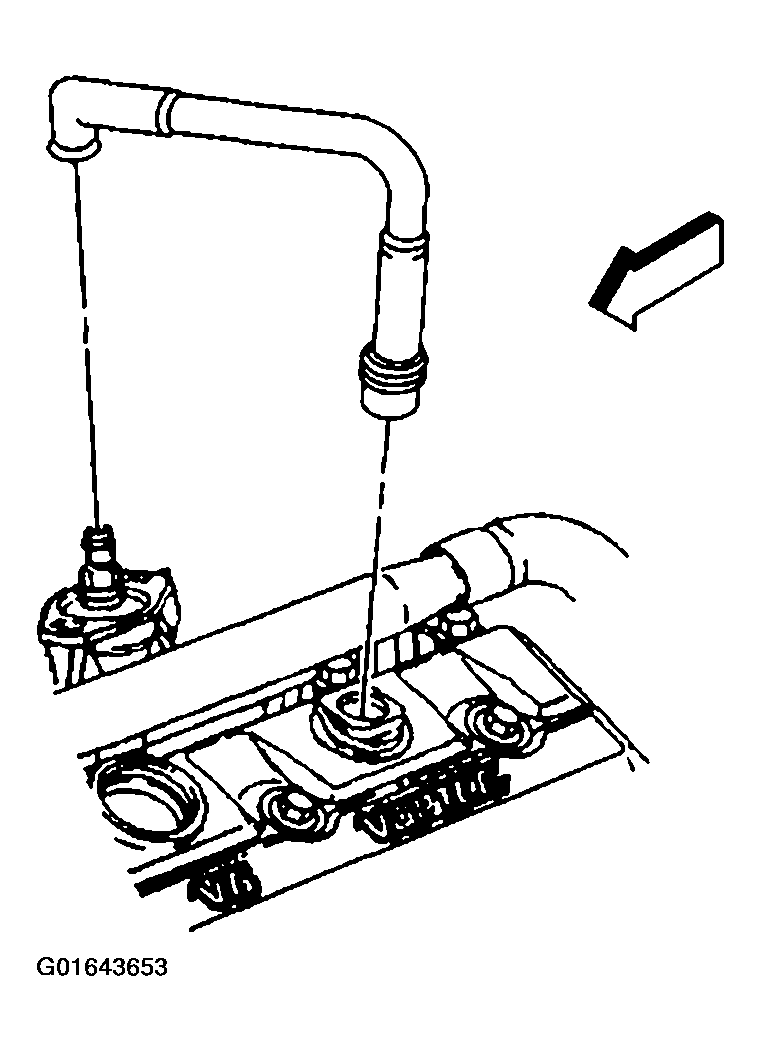
- Disconnect PCV valve hose assembly from the intake manifold and the valve rocker arm cover.
 Courtesy of GENERAL MOTORS CORP.
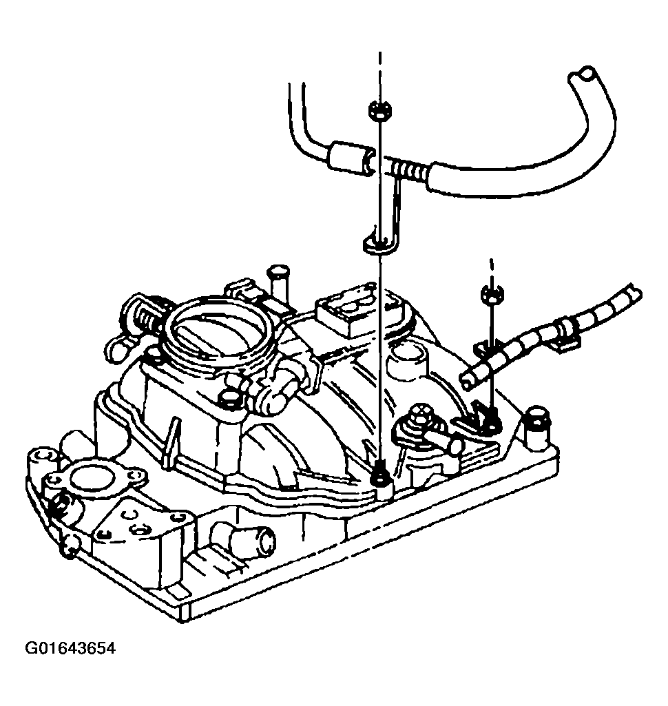
- Remove the nut holding the A/C hose bracket to the intake manifold stud, if equipped.
 Courtesy of GENERAL MOTORS CORP.
- Remove the nut holding the engine wiring harness bracket to the intake manifold stud.
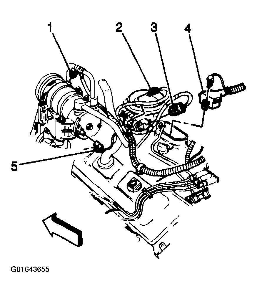
- Disconnect the following electrical connectors:
- The A/C compressor clutch, if equipped (1)
- The A/C high pressure cutoff switch, if equipped (5)
- The throttle position (TP) sensor (2)
- The idle air control (IAC) motor (3)
- The fuel meter body assembly connector (4)
 Courtesy of GENERAL MOTORS CORP.
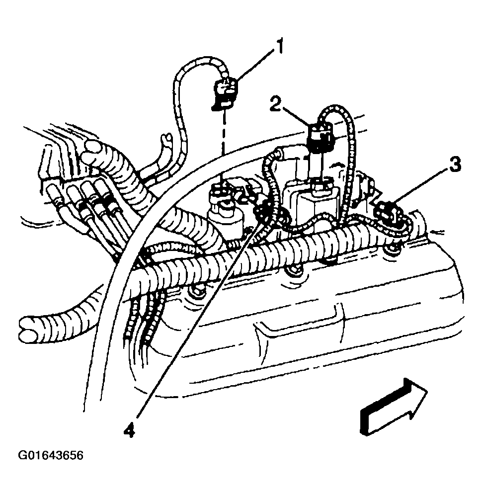
- Disconnect the following electrical connectors:
- The manifold absolute pressure (MAP) sensor (4)
- The EVAP canister purge solenoid valve (1)
 Courtesy of GENERAL MOTORS CORP.
- Remove the ground wire from the stud at the water outlet.
- Remove the nut, and remove the engine wiring harness bracket from the stud, at the EVAP canister purge solenoid valve.
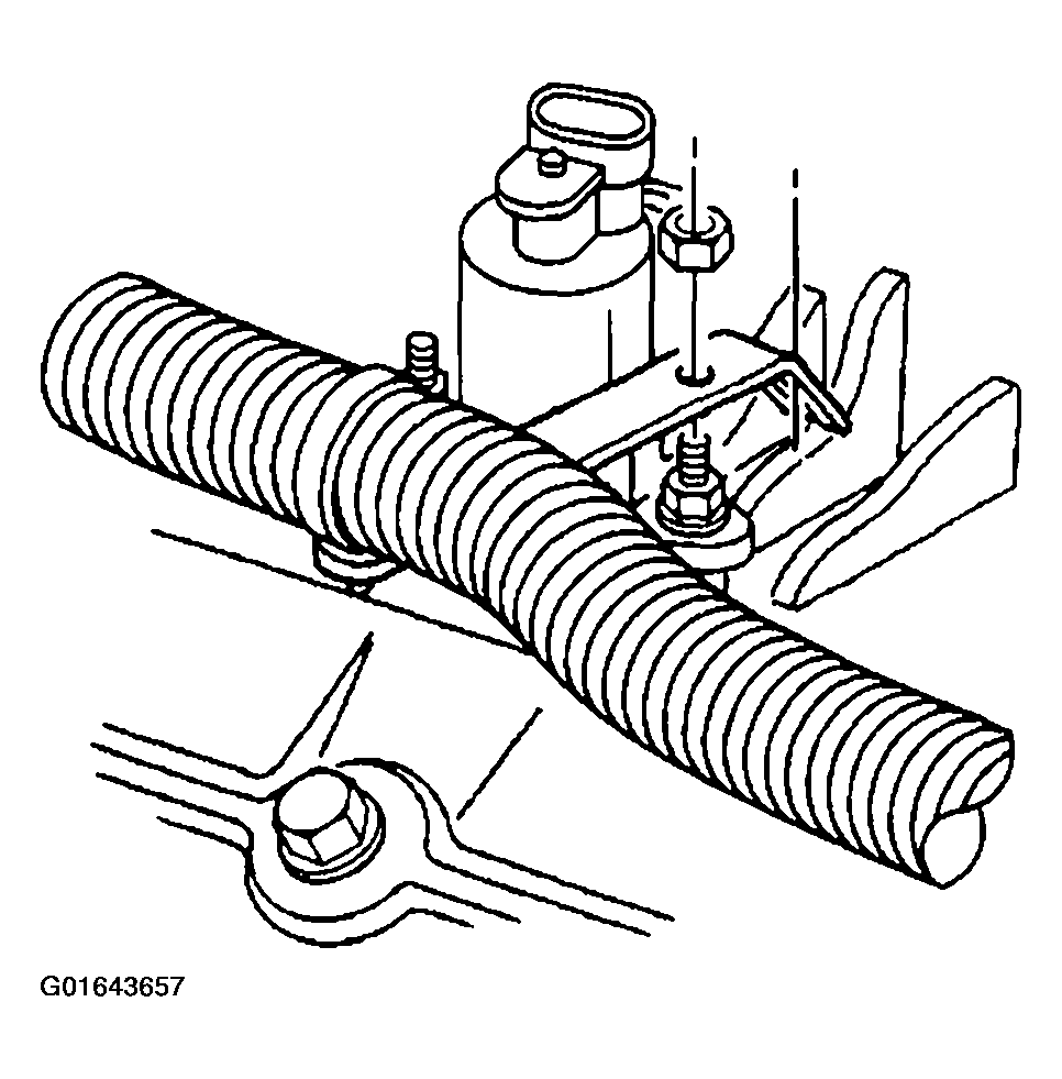 Courtesy of GENERAL MOTORS CORP.
- Move and secure the engine wire harness out of the way.
- Remove the EVAP canister purge valve. Refer to ENGINE CONTROLS - REMOVAL & INSTALLATION
in Engine Performance.
- Remove the radiator inlet hose at the water outlet. Refer to RADIATOR HOSE REPLACEMENT - INLET
in Engine Cooling.
- Remove the heater hose from the intake manifold. Refer to HEATER HOSE REPLACEMENT - INLET
in Heating Ventilation and Air Conditioning.
- Remove the water pump inlet hose from the intake manifold.
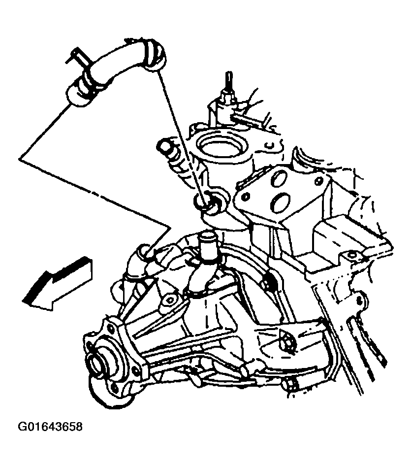 Courtesy of GENERAL MOTORS CORP.
- Disconnect the vacuum hose from the intake manifold.
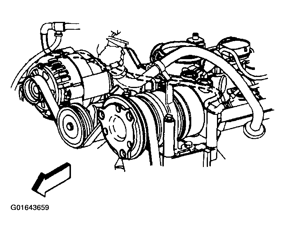 Courtesy of GENERAL MOTORS CORP.
- Remove the bolt holding the transmission fluid filler tube to the accelerator control cable bracket.
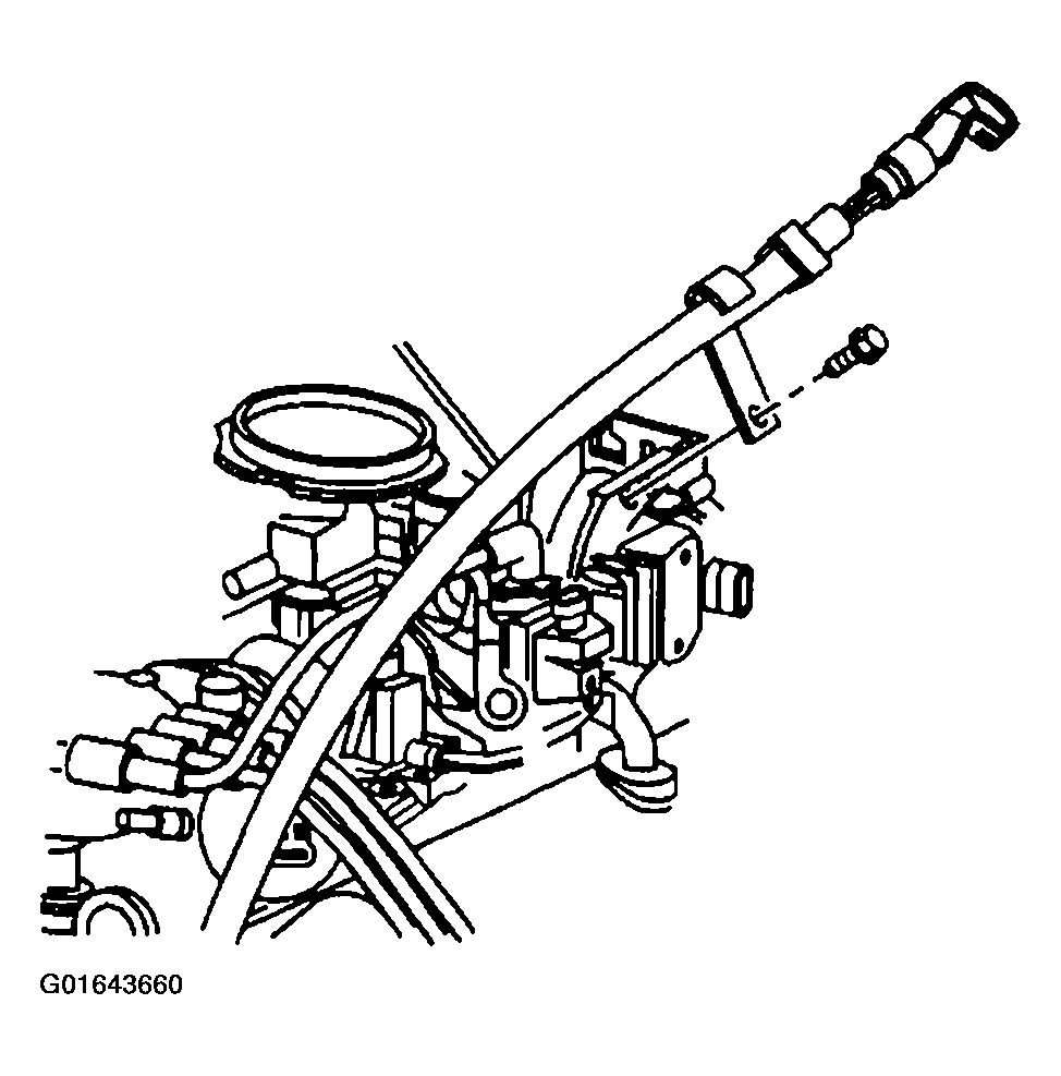 Courtesy of GENERAL MOTORS CORP.
- Remove the accelerator control cable bracket from the throttle body and the intake manifold.
- Remove the distributor. Refer to ENGINE CONTROLS - REMOVAL & INSTALLATION
in Engine Performance.
- Disconnect the fuel supply, and disconnect the return pipes, at the rear of the intake manifold. Refer to ENGINE CONTROLS - REMOVAL & INSTALLATION
in Engine Performance.
- Remove the ignition control module (ICM). Refer to ENGINE CONTROLS - REMOVAL & INSTALLATION
in Engine Performance.
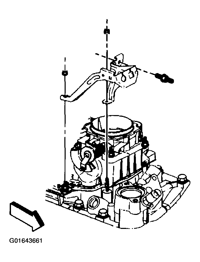 Courtesy of GENERAL MOTORS CORP.
- In order to remove the front intake manifold bolt, perform the following steps:
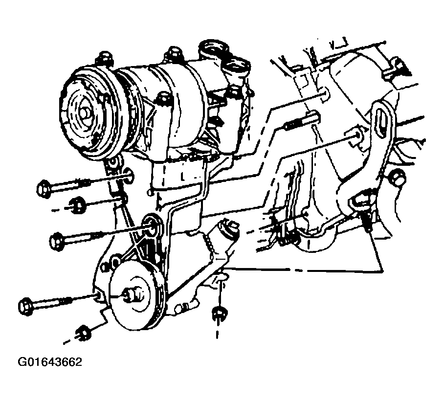 Courtesy of GENERAL MOTORS CORP.
- 26.1. Remove the drive belt. Refer to DRIVE BELT REPLACEMENT
.
- 26.2. Remove the A/C compressor side brace.
- 26.3. Loosen the nut for the power steering pump rear bracket.
- 26.4. Remove the oil filler tube bracket bolt and the oil filler tube.
- 26.5. Remove the bolts and the nut for the power steering pump mounting bracket.
- 26.6. Leave the A/C compressor, if equipped, and the power steering pump on the bracket.
- 26.7. Slide the power steering pump bracket forward to access the bolt at the front of the intake manifold.
- Remove the lower intake manifold. Refer to INTAKE MANIFOLD REPLACEMENT - LOWER
.
- Clean all sealing surfaces and the intake manifold. Refer to INTAKE MANIFOLD CLEANING AND INSPECTION
.
- If the intake manifold requires replacement, refer to INTAKE MANIFOLD DISASSEMBLE (LU3)
, and to INTAKE MANIFOLD ASSEMBLY (LU3)
.