Removal Procedure
- Remove the driver seat. Refer to SEAT REPLACEMENT - BUCKET
in Seats.
- Disconnect the battery cables, and remove the battery. Refer to BATTERY REPLACEMENT
in Engine Electrical.
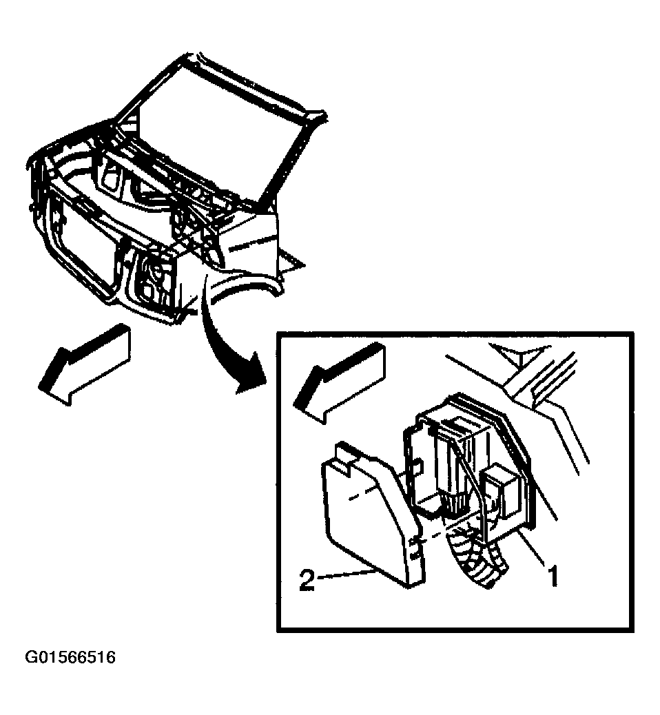
- Remove the bolt that retains the underhood fuse block to the bulkhead.
- Disable the SIR system. Refer to DISABLING & ACTIVATING AIR BAG SYSTEM
in SIR.
- Remove the face-plate (2) from the outer housing of the junction block (1).
 Courtesy of GENERAL MOTORS CORP.
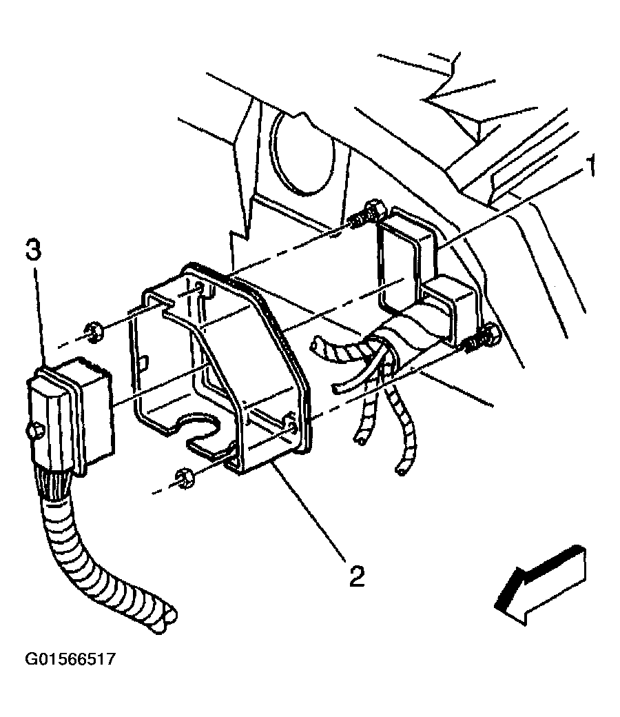
- Disconnect the engine harness electrical connector (3) from the junction block (1).
 Courtesy of GENERAL MOTORS CORP.
- Separate the outer housing of the junction block (2) from the bulkhead.
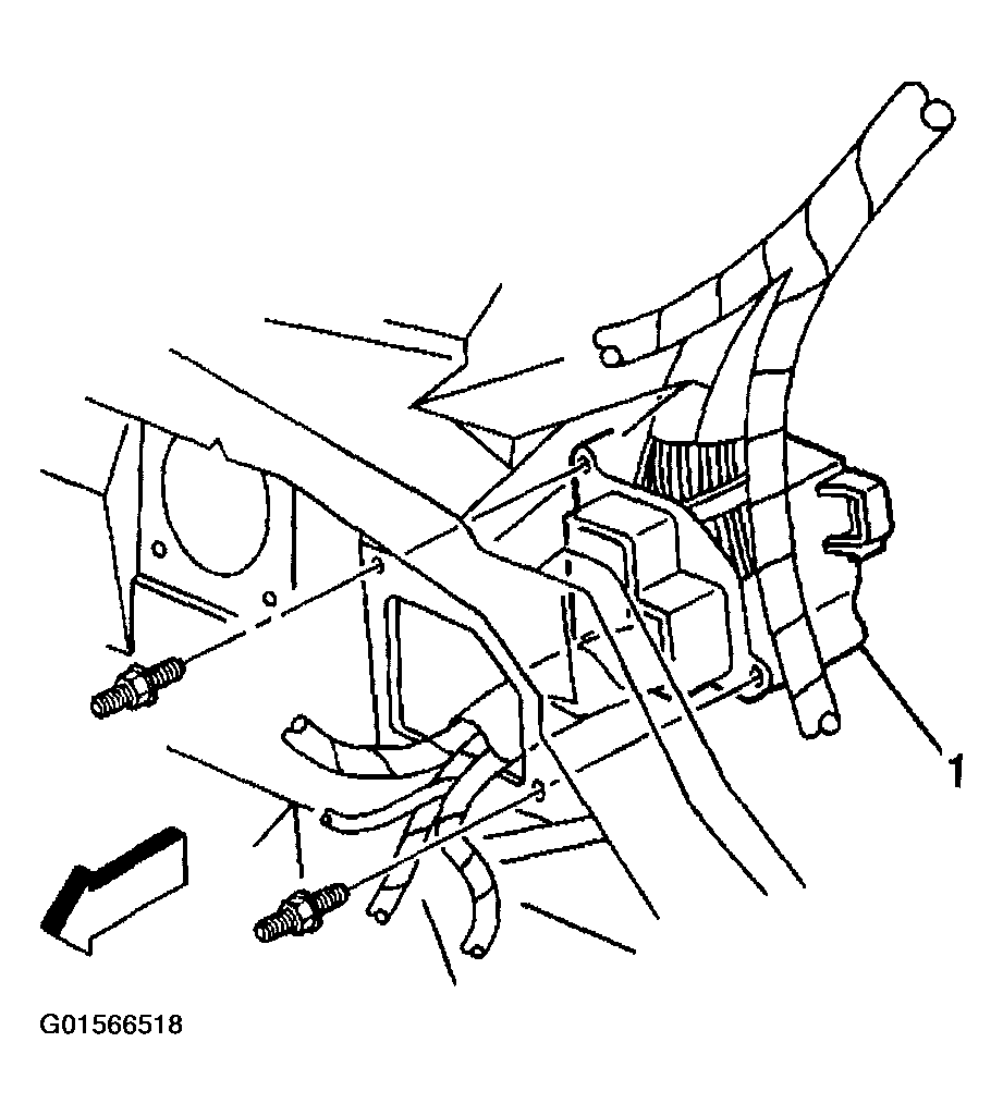
- Remove the 2 studs that retain the junction block (1) to the bulkhead.
 Courtesy of GENERAL MOTORS CORP.
- Remove the junction block from the bulkhead.
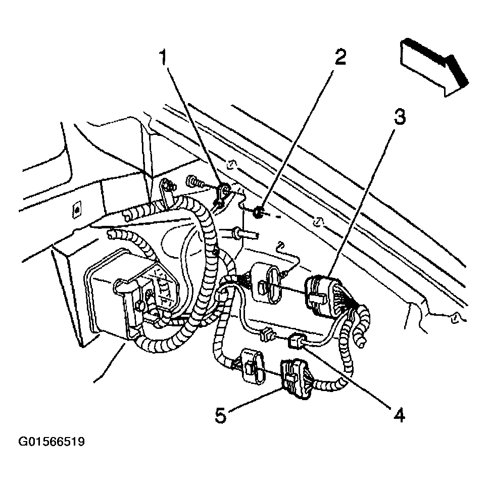
- Remove the nut (2) that retains the I/P harness grounding strap (1) to the body.
- Remove the I/P harness grounding strap (1) from the body.
- Disconnect the I/P from the forward lamp harness connector (3).
 Courtesy of GENERAL MOTORS CORP.
- Disconnect the forward lamp from the I/P harness connector (4).
- Disconnect the engine from the forward lamp harness connector (5).
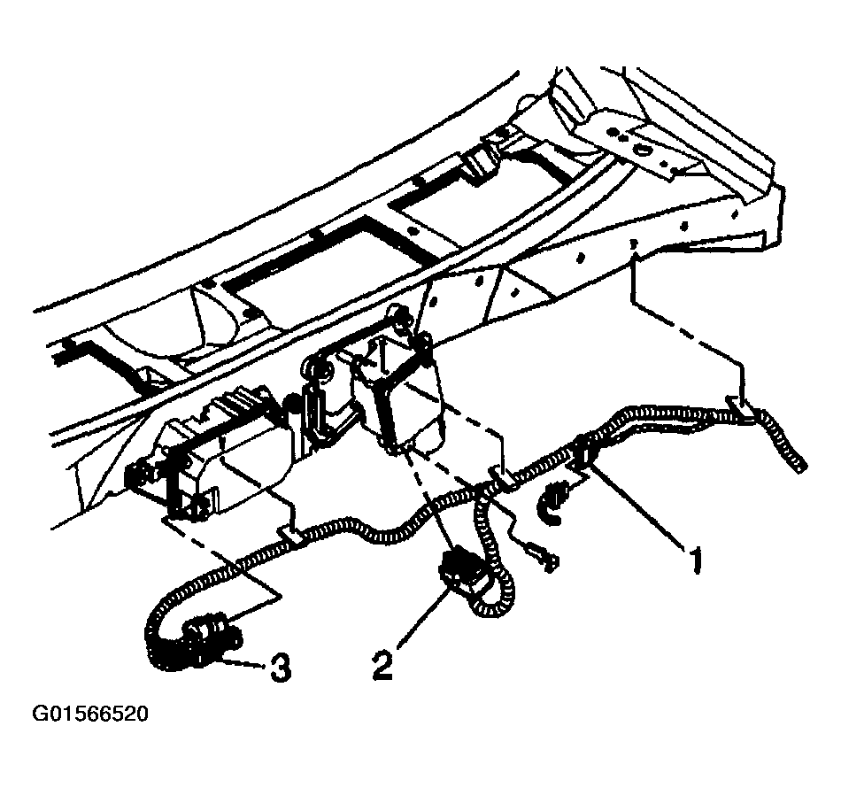
- Disconnect the electrical connector of the cruise control module (3).
- Disconnect the electrical connector of the windshield wiper motor (2).
- Disconnect the electrical connector of the rear lamp wiring harness (1).
 Courtesy of GENERAL MOTORS CORP.
- Remove the power steering fluid reservoir from the bulkhead. Refer to REMOTE POWER STEERING FLUID RESERVOIR REPLACEMENT
in Power Steering System.
- Remove the cruise control module from the bulkhead. Refer to CRUISE CONTROL MODULE REPLACEMENT
in Cruise Control.
- Note the routing of the I/P wire harness on the engine side of the bulkhead. Remove the I/P wire harness from the bulkhead.
- Remove the I/P extension from the vehicle. Refer to INSTRUMENT PANEL (I/P) EXTENSION REPLACEMENT .
- Remove the engine cover from the vehicle. Refer to ENGINE COVER REPLACEMENT
in Interior Trim.
- Remove the driver knee bolsters and the passenger knee bolsters. Refer to KNEE BOLSTER REPLACEMENT - RIGHT or to KNEE BOLSTER REPLACEMENT - LEFT .
- Remove cowl trim panels on the right side, and on the left side. Refer to TRIM PANEL REPLACEMENT - COWL SIDE
in Interior Trim.
- Remove the left carpet retainers and the right carpet retainers. Refer to CARPET RETAINER REPLACEMENT
in Interior Trim.
- Remove the HVAC floor vent cover that is located behind the driver seat. Refer to AIR OUTLET REPLACEMENT - REAR FLOOR
in Heating, Ventilation and Air Conditioning.
- Lift the carpet in order to access the sensing and diagnostic module (SDM).
- Disconnect the CPA and the electrical connector from the SDM.
- Feed the seat wire harnesses through the access hole in the carpet.
- Remove the SDM and the seat wire harness from the trough along the left door sill.
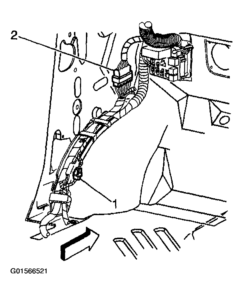
- Disconnect the 16-way I/P from the body harness (2).
- Disconnect the 10-way I/P from the body harness (1).
 Courtesy of GENERAL MOTORS CORP.
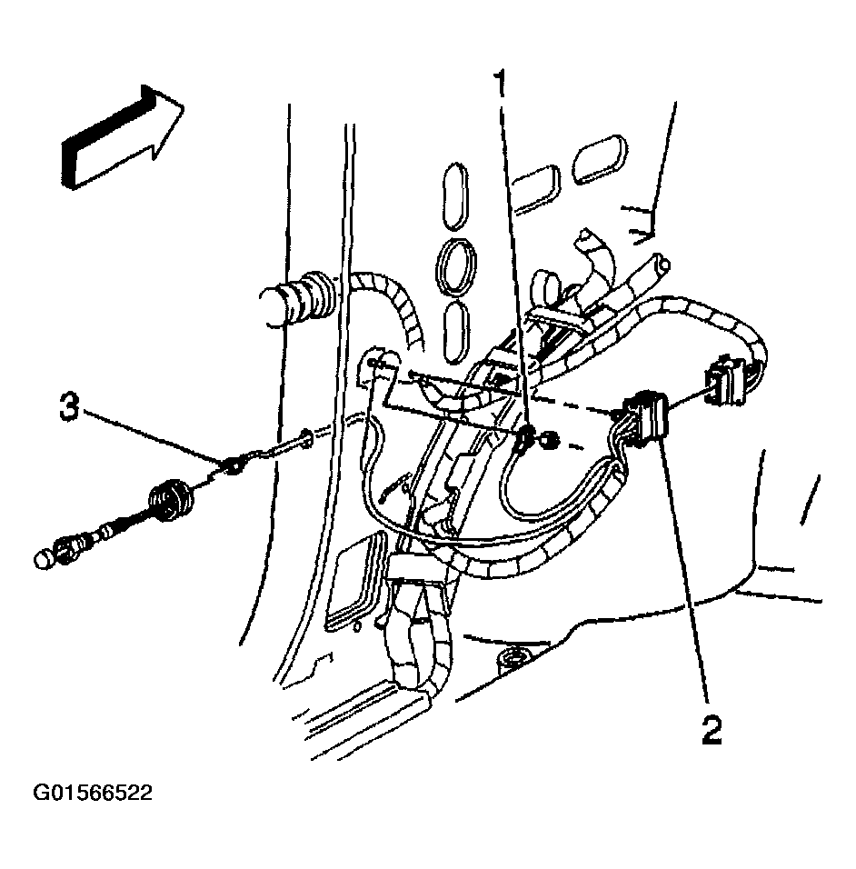
- Disconnect the ground strap harness for the left door (1).
- Disconnect the left door harness connector (2).
- Disconnect the door jamb switch connector on the left (3).
 Courtesy of GENERAL MOTORS CORP.
- Release the harness straps in order to remove the harnesses from the trough.
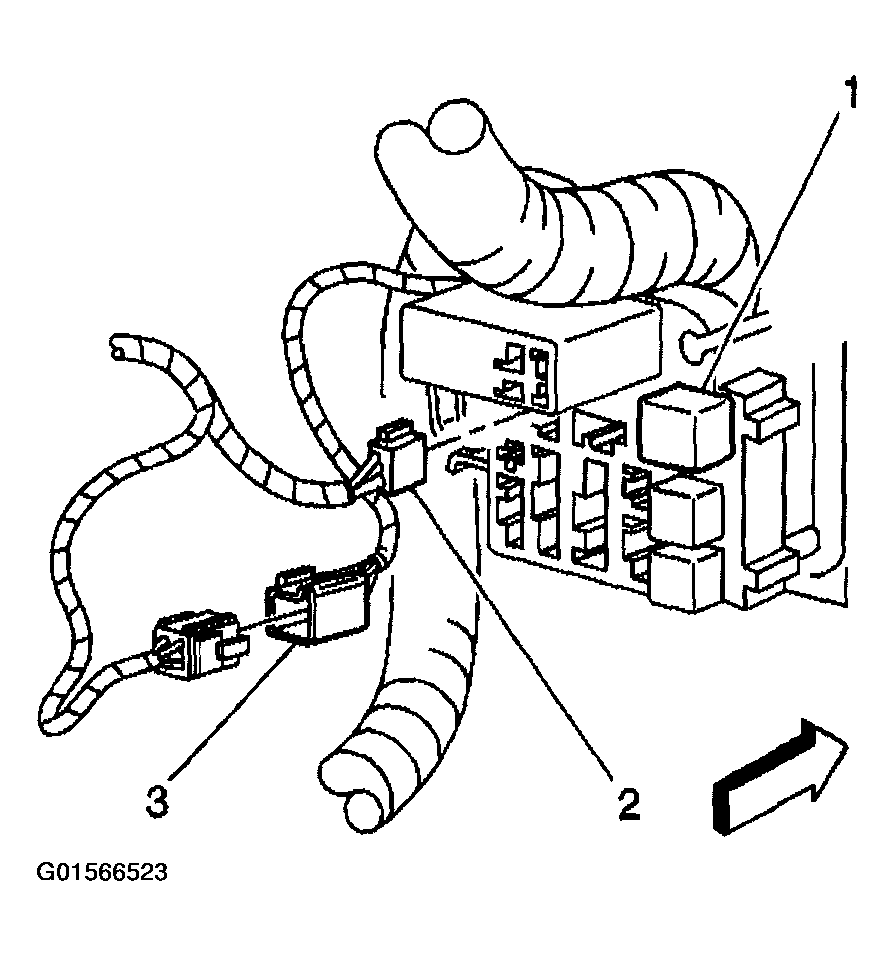
- Disconnect the headliner connector (2) from the I/P junction block.
 Courtesy of GENERAL MOTORS CORP.
- Disconnect the heater jumper connector (3) from the body harness.
- Remove the electrical connector of the power seat harness from the I/P junction block.
- Disconnect the electrical connector of the park brake from the park brake switch. Refer to DISC BRAKES
in Park Brake.
- Remove the black 6-way connector from the I/P junction block.
- Disconnect the roof console harness connector (1) from the I/P junction block.
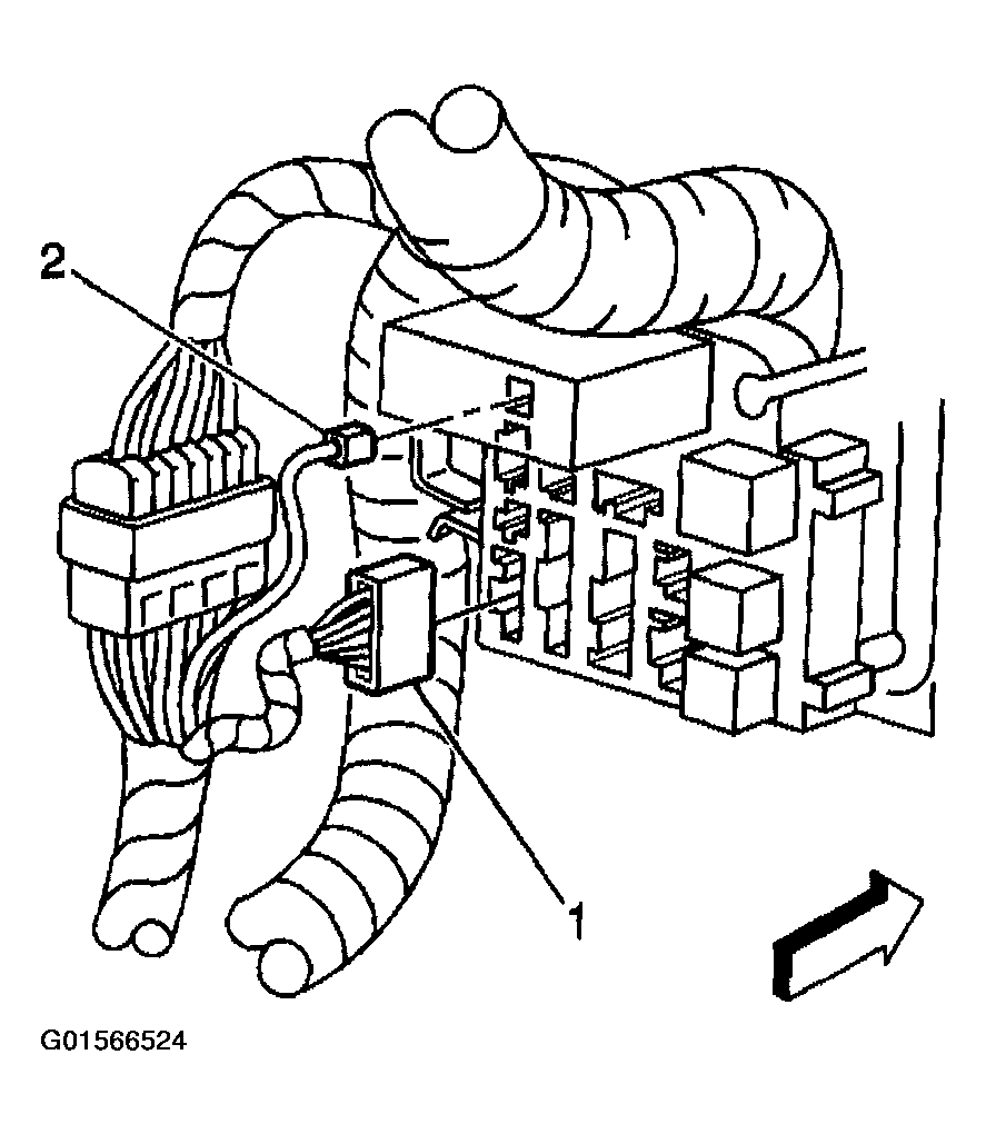 Courtesy of GENERAL MOTORS CORP.
- Disconnect the trailer wiring harness connector (2) from the I/P junction block.
- Disconnect the orange 3-way in-line connector (1).
- Disconnect the black 5-way in-line connector.
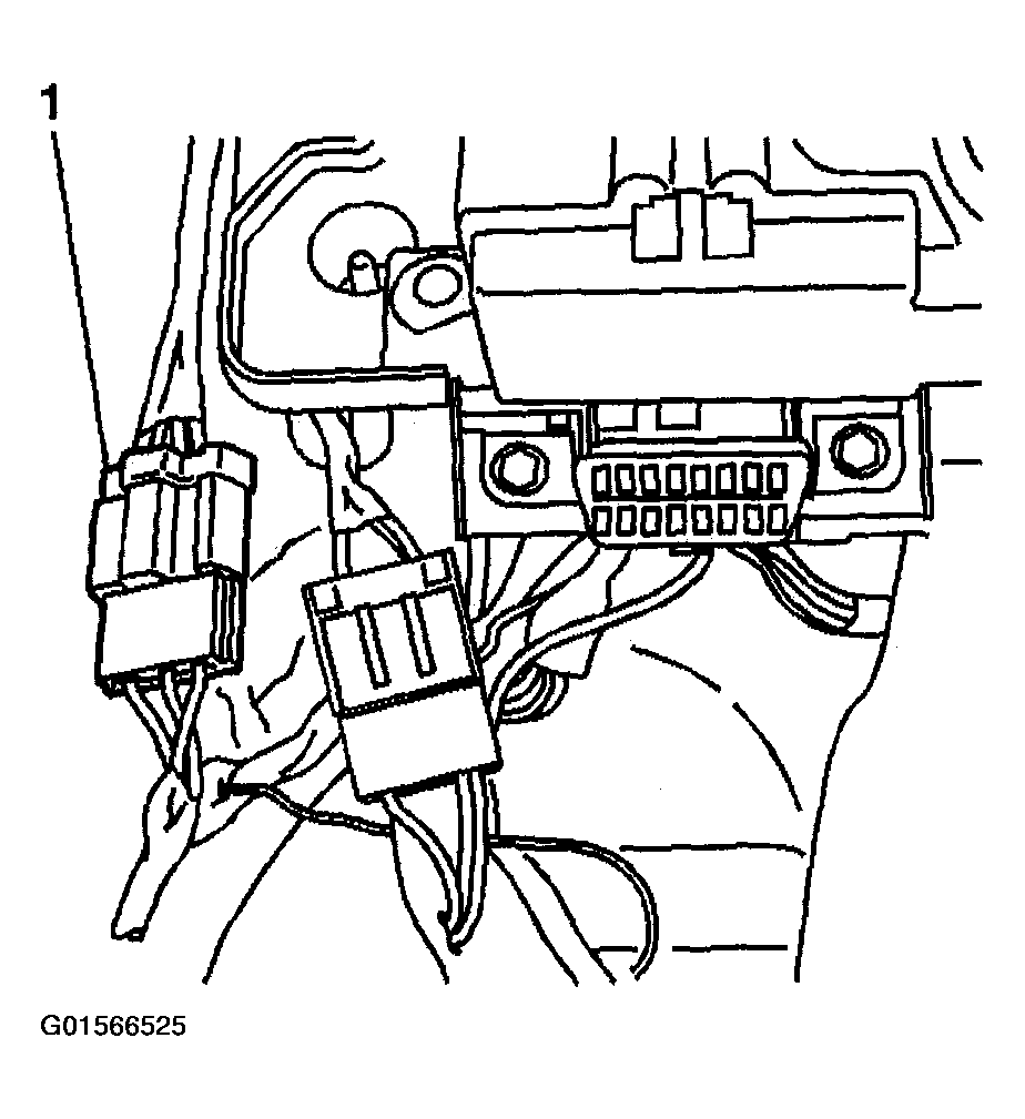 Courtesy of GENERAL MOTORS CORP.
- Disconnect the brake switch electrical connector.
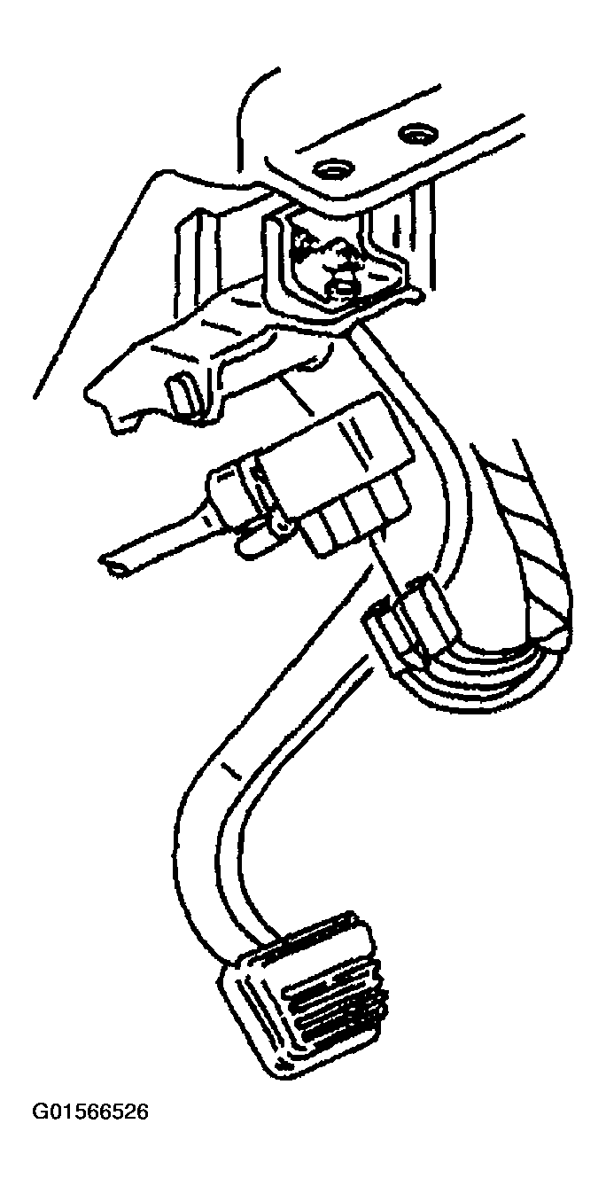 Courtesy of GENERAL MOTORS CORP.
- Remove the air outlet duct from the left lap. Refer to AIR OUTLET DUCT REPLACEMENT - LEFT LAP
in Heating, Ventilation and Air Conditioning.
- Remove the bolts that are retaining the left lap bracket of the air outlet duct to the I/P carrier.
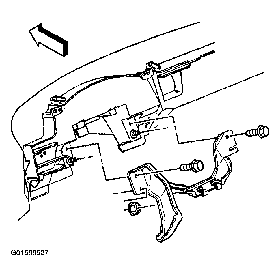 Courtesy of GENERAL MOTORS CORP.
- Remove the left lap bracket of the air outlet duct from the I/P carrier.
- Disconnect the steering column harness connector by loosening the bolt (2) in the center of the connector.
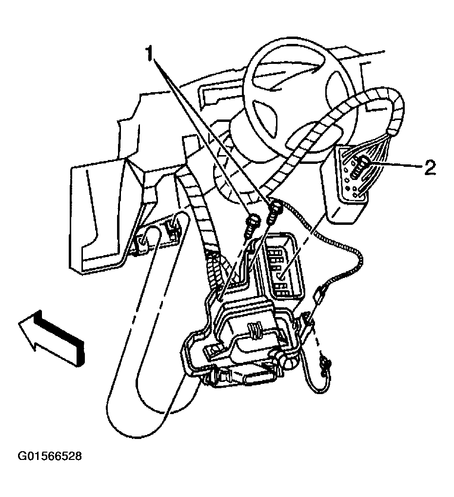 Courtesy of GENERAL MOTORS CORP.
- Remove the steering column from the I/P carrier. Refer to STEERING COLUMN REPLACEMENT
in Steering Wheel and Column.
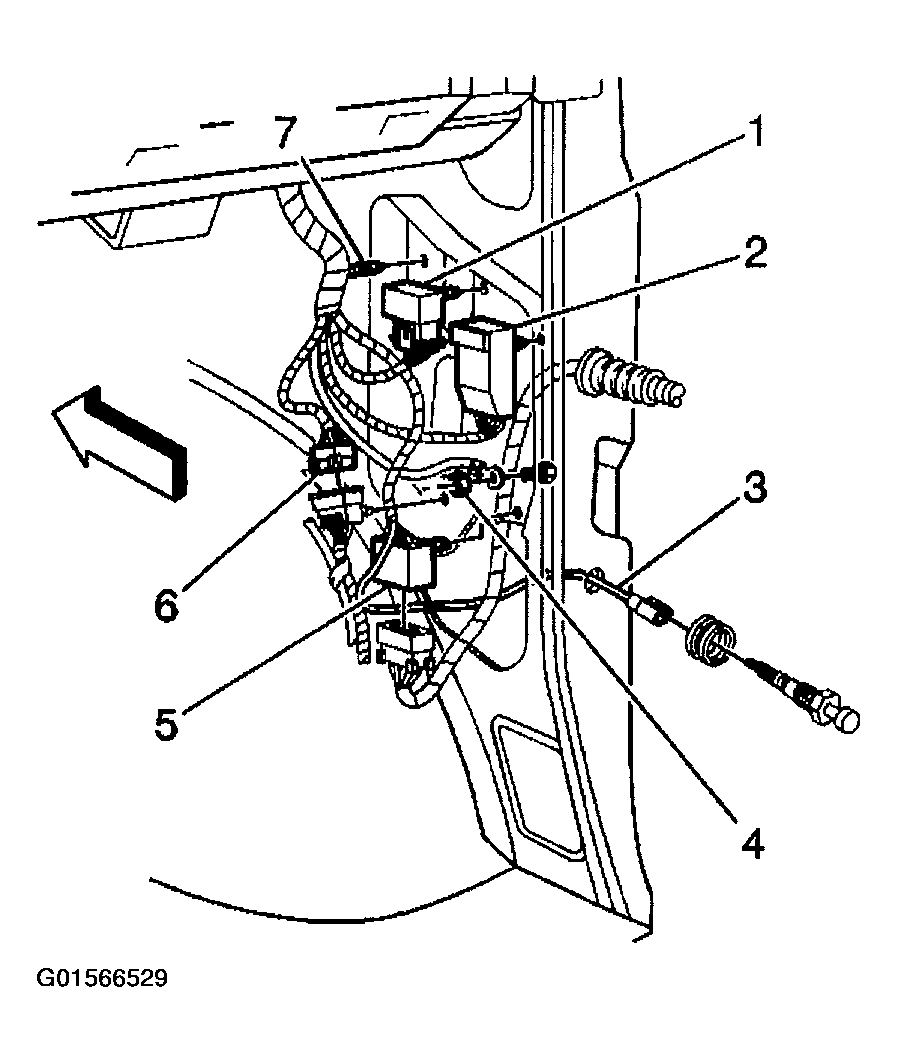
- In order to remove the right I/P harness, disconnect the following components:
- The door lock relay harness (1)
- The door jamb switch harness (3)
- The ground terminal harness (4)
- The I/P door connector harness (5)
- The liftgate connector harness (6)
- The I/P harness fastener (7)
 Courtesy of GENERAL MOTORS CORP.
- Remove the fastener that is retaining the door lock control module (2) to the body.
- Disconnect the HVAC actuator, which is a black 5-way connector, and the vacuum lines.
- Remove the I/P cluster trim panel. Refer to TRIM PANEL REPLACEMENT - INSTRUMENT PANEL (I/P) CLUSTER .
- Remove the radio. Refer to RADIO REPLACEMENT
in Entertainment.
- Remove the HVAC control assembly. Refer to HVAC CONTROL ASSEMBLY REPLACEMENT
in Heating, Ventilation and Air Conditioning.
- Remove the I/P cluster. Refer to INSTRUMENT PANEL CLUSTER (IPC) REPLACEMENT .
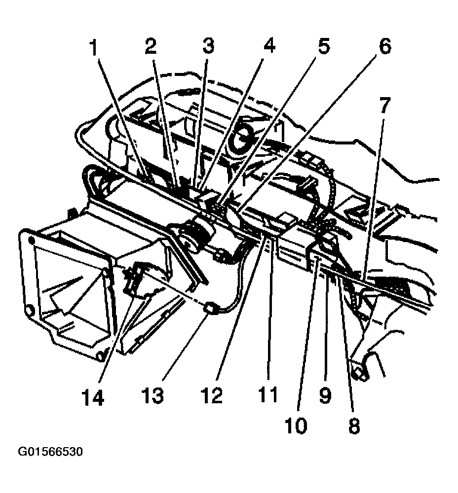 Courtesy of GENERAL MOTORS CORP.
- Locate the instrument panel that retains the I/P carrier to the carrier support brackets. Remove the 2 bolts on the left sides and on the right sides of the instrument panel.
- Slide the instrument panel away from the bulkhead.
- Lift the instrument panel up and off the pivot points.
- Remove the I/P assembly from the vehicle.
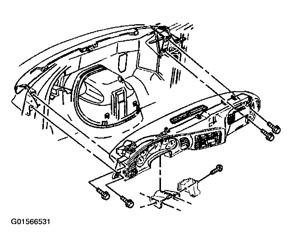 Courtesy of GENERAL MOTORS CORP.
- Place the I/P assembly on a clean surface.
- In order to remove the I/P from the I/P carrier, perform the remaining steps of this procedure. Remove the center defogger grille from the I/P.
- Remove the ambient light sensor of the daytime running lamps (DRL). Refer to DAYTIME RUNNING LAMPS (DRL) AMBIENT LIGHT SENSOR REPLACEMENT
in Lighting Systems.
- Remove the HVAC ducts from the I/P assembly. Refer to AIR OUTLET DUCT REPLACEMENT - LEFT FLOOR
in Heating, Ventilation and Air Conditioning.
- From the rear of the I/P, remove the 5 screws that retain the top of the I/P to the carrier.
- Remove the body control module (BCM) from the BCM bracket. Refer to BODY CONTROL MODULE REPLACEMENT
in Body Control System.
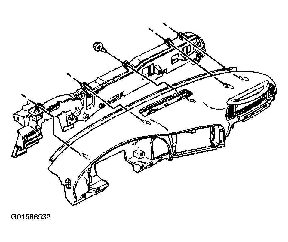 Courtesy of GENERAL MOTORS CORP.
- Remove the remote keyless entry receiver from the I/P substrate. Refer to REMOTE CONTROL DOOR LOCK RECEIVER REPLACEMENT
in Keyless Entry.
- From the front of the I/P, remove the 6 screws that retain the bottom of the I/P to the carrier.
- Remove the I/P inflatable restraint. Refer to SUPPLEMENTAL INFLATABLE RESTRAINT SYSTEM
in SIR.
- Remove the I/P from the I/P carrier.
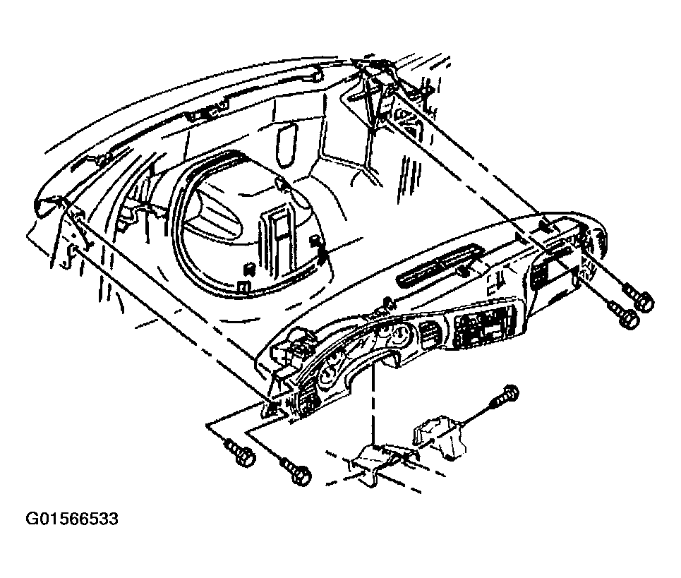 Courtesy of GENERAL MOTORS CORP.