Test R: Abs Indicator Inoperative/Always On
- Turn ignition switch to RUN position. If ABS indicator does not illuminate, go to next step. If ABS indicator is always illuminated, repair anti-lock brake system as necessary. See appropriate ANTI-LOCK article in BRAKES.
- Turn ignition switch to LOCK position. Disconnect Black 30-pin ABS module harness connector C141. ABS module is located in right front of engine compartment, behind radiator. Connect a fused jumper wire between ground and ABS module harness connector C141 terminal No. 16 (Dark Green wire). See Fig 1
. Turn ignition switch to RUN position. If ABS indicator does not illuminate, go to next step. If ABS indicator illuminates, repair anti-lock brake system as necessary. See appropriate ANTI-LOCK article in BRAKES.
- Turn ignition switch to LOCK position. Disconnect 20-pin instrument cluster harness connector C251. It may be necessary to remove instrument cluster for access to connector. See REMOVAL & INSTALLATION
. Measure resistance in Dark Green wire between ABS module harness connector C141 terminal No. 16 and instrument cluster harness connector C251 terminal No. 15. See Figure
and Fig 1
. If resistance is 5 ohms or less, go to next step. If resistance is more than 5 ohms, repair open in Dark Green wire between instrument cluster and ABS module. See WIRING DIAGRAMS
.
- Disconnect all instrument cluster harness connectors. Inspect all instrument cluster harness connectors for loose, damaged or corroded terminals. If terminals are damaged, repair as necessary. If terminals are not damaged, reconnect all instrument cluster harness connectors. Ensure instrument cluster harness connectors are seated properly. If problem still exists, replace instrument cluster module.
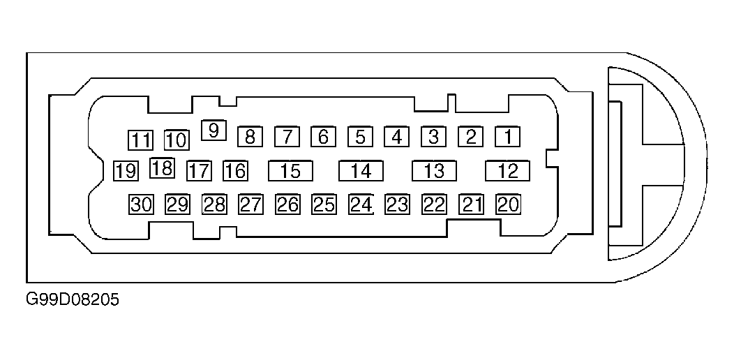 Courtesy of FORD MOTOR CO.