Test M: Service Engine Soon Warning Indicator Inoperative
- Turn ignition switch to LOCK position. Disconnect PCM 104-pin harness connector C1027. Turn ignition switch to ON position. Connect a 10-amp fused jumper wire between PCM harness connector C1027 terminals No. 2 (Pink/Light Green wire) and No. 24 (Black/White wire). See Fig 1. If SERVICE ENGINE SOON indicator does not illuminate, go to next step. If SERVICE ENGINE SOON indicator illuminates, diagnose PCM problem. See appropriate SELF-DIAGNOSTICS article in ENGINE PERFORMANCE.
- Turn ignition switch to LOCK position. Remove instrument cluster to gain access to instrument cluster harness connectors. See REMOVAL & INSTALLATION . Remove SERVICE ENGINE SOON indicator bulb. Measure resistance between SERVICE ENGINE SOON indicator bulb terminals. If bulb is okay, go to next step. If bulb is not okay, replace bulb. Retest system operation.
- Disconnect instrument cluster 12-pin harness connector C250C. Measure resistance of Pink/Light Green wire between instrument cluster 12-pin harness connector C250C terminal No. 5 and PCM 104-pin harness connector C1027 terminal No. 2. See Figure and Fig 1
. If resistance is 5 ohms or less, replace instrument cluster. Retest system operation. If resistance is more then 5 ohms, repair open in Pink/Light Green wire between instrument cluster and PCM. See WIRING DIAGRAMS . Retest system operation.
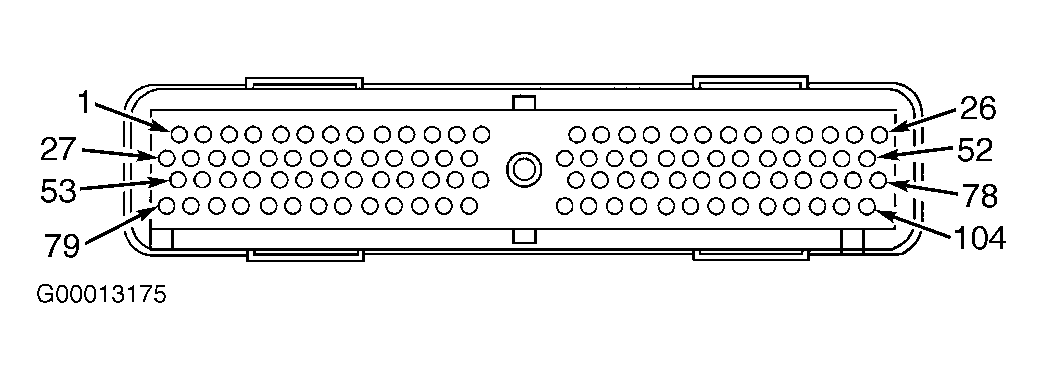 Courtesy of FORD MOTOR CO.