Test S: No Communication With Natural Gas Vehicle Module
- Turn ignition switch to LOCK position. Disconnect Natural Gas Vehicle (NGV) module harness connector C1012. Measure voltage between ground and terminal No. 1 (Yellow/Black wire) at NGV module harness connector C1012. See Fig 1. If battery voltage exists, go to next step. If battery voltage is not present, go to step 5.
- Remove fuse No. 25 (20-amp) from battery junction box. Measure resistance between ground and terminal No. 1 (Yellow/Black wire) at NGV module harness connector C1012. If resistance is more than 10 k/ohms, go to next step. If resistance is 10 k/ohms or less, repair short to ground in Yellow wire between output of fuse No. 25 and NGV harness connector.
- Measure voltage between ground and input side (inside terminal) of fuse No. 25 (20-amp) at battery junction box. If battery voltage exists, go to next step. If battery voltage is not present, repair open Yellow wire between output of fuse No. 25 and NGV harness connector.
- Measure resistance in Yellow wire between terminal No. 1 at NGV module harness connector C1012 and output side terminal of fuse No. 25 (20-amp) at battery junction box. If resistance is 5 ohms or less, replace fuse No. 25 (20-amp) and retest system. If resistance is more than 5 ohms, repair open in Yellow wire between output of fuse No. 25 and NGV harness connector.
- Turn ignition switch to RUN position. Measure voltage between ground and terminals No. 37 and 57 (Red wires) at NGV module harness connector C1012. If battery voltage exists, go to next step. If battery voltage is not present, repair appropriate open Red wire. Red wire runs from terminal No. 87 at PCM power relay, splice S180 (located at left rear of engine compartment, above master cylinder) and branches to terminals No. 37 and 57 at NGV module harness connector.
- Turn ignition switch to LOCK position. Measure resistance between ground and terminals No. 40 and 60 (Black wires) at NGV module harness connector C1012. If resistance is 5 ohms or less, go to
MODULE COMMUNICATIONS NETWORK - ECONOLINE article. If resistance is more than 5 ohms, repair open in appropriate Black wire. Black wire runs from terminal No. 1 at NGV timer harness connector C1013, splice S188 (located in clean air tube, on intake air temperature sensor) and branches to terminals No. 40 and 60 at NGV module harness connector.
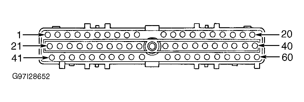 Courtesy of FORD MOTOR CO.