Circuit Function
WARNING: This page does not describe the selected car, but rather 9 other vehicles, including the 2004 Ford RV Cutaway, 2004 Ford Pickup, 2004 Ford F550 Super Duty, 2004 Ford F450 Super Duty, and 2004 Ford Excursion. However, it is still accessible from the selected car via links, so may be relevant.
The 6.0L diesel speed control function is integrated into the powertrain control module (PCM). The momentary -contact steering wheel mounted switches are hardwired to the PCM. Pressing and releasing the ON switch turns the system on. Pressing and releasing the SET/ACCEL switch with the system on and a vehicle speed greater than 40 km/h (25 mph) activates the system. Tapping the SET/ACCEL or COAST switches increases or decreases the vehicle speed by 1.6 km/h (1 mph) per tap. If the respective switch is pressed and held, vehicle speed will accelerate or decelerate until the switch is released. Pressing and releasing the OFF switch or turning the ignition switch to the OFF position will deactivate the system. Standby mode is achieved with the application of the brake pedal. Pressing the RESUME switch with the system in standby mode will increase the vehicle speed until the last set speed is achieved.
CAUTION:
The PCM harness connectors must be properly seated and the connector latch properly attached to eliminate possible driveability concerns or a no-start condition. Installing PCM connectors on an angle may cause an improper connection, misdiagnosis, and damaged components. Install the connector until the lever pivots and seats itself. Apply light pressure to get the connector into position on the PCM and then fully seat the connector.
NOTE:
Visually inspect the harness connectors for corrosion, damage, proper mating and correct pin tension.
NOTE:
When the PCM is disconnected additional DTCs will be set. Clear all DTCs after restoring the vehicle.
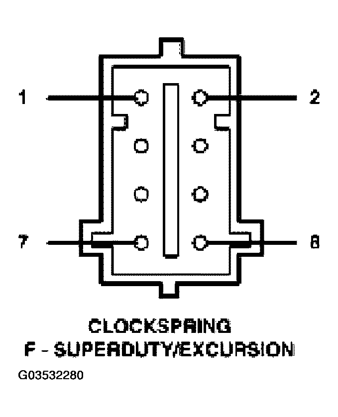 Courtesy of FORD MOTOR CO.
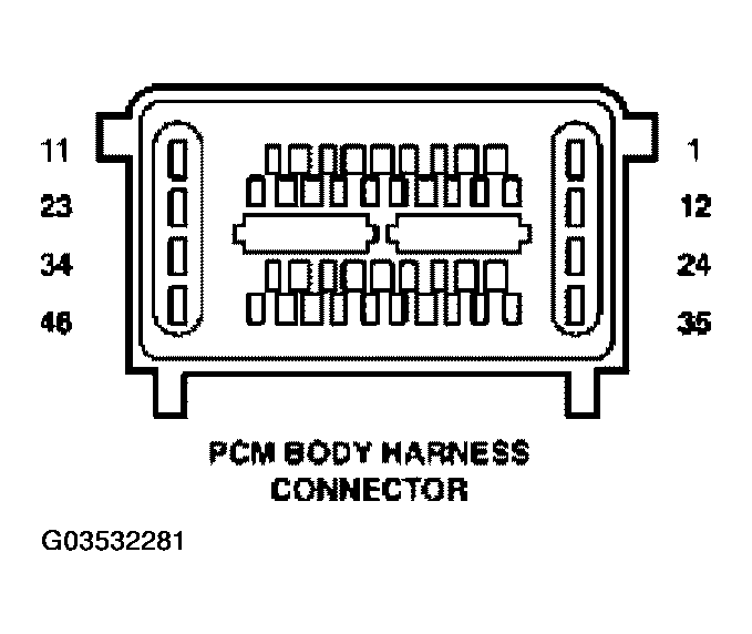 Courtesy of FORD MOTOR CO.
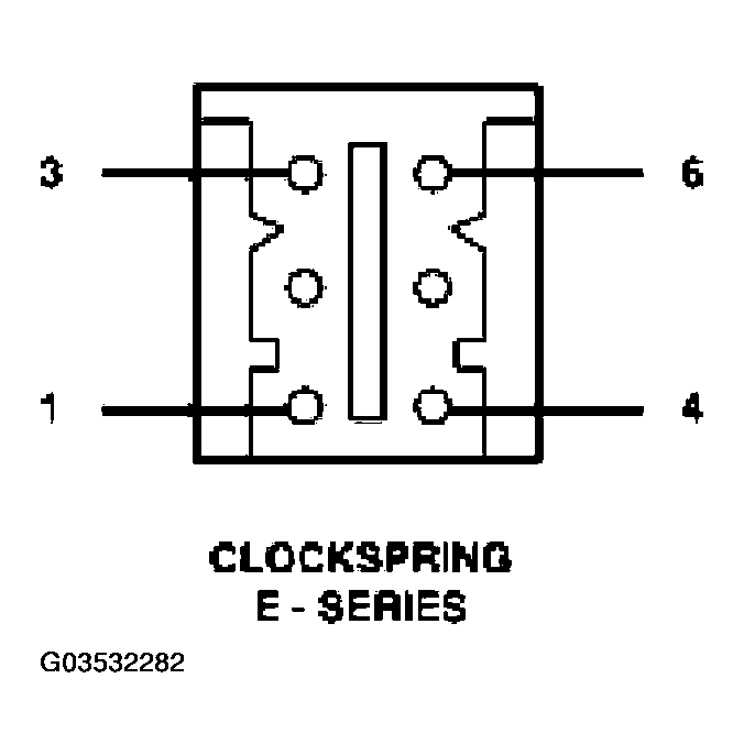 Courtesy of FORD MOTOR CO.