Test B: Fuel Gauge Reads Inaccurately
- Turn ignition switch to RUN position. If instrument cluster warning indicators and gauges are not operating, perform TEST A: WARNING LIGHTS & GAUGES INOPERATIVE
. If instrument cluster warning indicators and gauges are operating, go to next step.
- Turn ignition switch to LOCK position. Disconnect fuel sending unit harness connector C732. Turn ignition switch to RUN position. If fuel gauge indicates full, go to next step. If fuel gauge does not indicate full, go to step 4
.
- Turn ignition switch to LOCK position. Using a jumper wire, ground terminal No. 5 (White/Red wire) at fuel sending unit harness connector C732. See Fig 1
. If fuel gauge does not indicate empty, go to step 8
. If fuel gauge indicates empty, replace fuel sending unit.
- Turn ignition switch to LOCK position. Disconnect instrument cluster harness connector C808B. Measure resistance between ground and terminal No. 7 (White/Red wire) at instrument cluster harness connector C808B. See Figure
. If resistance is more than 10 k/ohms, go to next step. If resistance is 10 k/ohms or less, repair short to ground in White/Red wire.
- Disconnect remaining instrument cluster harness connectors. Remove instrument cluster. Measure resistance between terminal No. 7 (White/Red wire) at instrument cluster harness connector C808B (component side) and fuel gauge terminal F3 on printed circuit. See Fig 2
. If resistance is 5 ohms or less, go to next step. If resistance is more than 5 ohms, replace printed circuit.
- Measure resistance between terminal No. 4 (Black/Orange wire) at instrument cluster harness connector C808B (component side) and fuel gauge terminal F2 on printed circuit. If resistance is 5 ohms or less, go to next step. If resistance is more than 5 ohms, replace printed circuit.
- Measure resistance between speedometer terminal S2 on printed circuit and fuel gauge terminal F1 on printed circuit. See Fig 3
. If resistance is 5 ohms or less, replace instrument cluster or fuel gauge as necessary. If resistance is more than 5 ohms, replace printed circuit.
- Turn ignition switch to LOCK position. Measure resistance of White/Red wire between terminal No. 7 at instrument cluster harness connector C808B and terminal No. 5 at fuel sending unit harness connector C732. See Figure
and Fig 1
. If resistance is 5 ohms or less, check Black/Blue wire between fuel sending unit harness connector terminal No. 4 and ground for an open and repair as necessary. If Black/Blue wire is okay, replace instrument cluster. If resistance is 5 ohms or more, repair open White/Red wire.
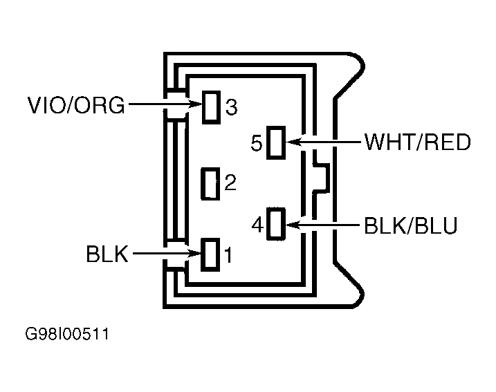 Courtesy of FORD MOTOR CO.
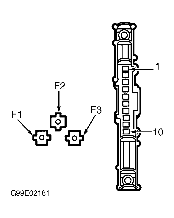 Courtesy of FORD MOTOR CO.
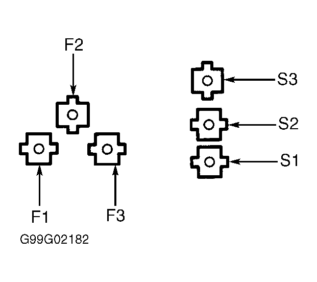 Courtesy of FORD MOTOR CO.