Mark VII, Sable & Taurus
- Ensure all bulbs and fuses are good before proceeding. Remove headlight switch. See HEADLIGHT SWITCH R & I under REMOVAL & INSTALLATION. Test headlight switch positions for continuity. See Fig 1.
- Reconnect headlight switch. Using test light, backprobe connector between terminals B1 and body ground. If test light does not glow, repair open in Black/Orange wire from fusible link "D". See appropriate WIRING DIAGRAMS in this article.
- Using test light, backprobe connector between terminal B2 and body ground. If test light does not glow, repair open in Tan/White wire to fuse block fuse No. 4.
- Using jumper wire, connect terminals B1 and "H". If headlights do not operate, check for the following and repair as required. See appropriate WIRING DIAGRAMS in this article.
- Open in Red/Yellow wiring to dimmer switch
- Faulty dimmer switch
- Open in high beam Light Green/Black wiring to both headlights
- Open in low beam Red/Black wiring to both headlights
- Open in ground circuit to headlights
- Using jumper wire, connect terminals B2 and "R". If rear lights and all parking lights do not light, repair open in Brown wiring. If no problem exists in these circuits, repair ground circuit to rear lights. See appropriate WIRING DIAGRAMS in this article.
- Circuit "R" also powers LCD dimming relay. If rotating dimmer control does not vary panel brightness, repair open in Brown wire between headlight switch terminal "R" and LCD dimming relay. LCD dimming relay is located behind center of instrument panel, near left side of glove box. Access relay through glove box opening.
- Using test light, backprobe connector between IGN (ignition) terminal and body ground. With ignition switch in ACC or RUN position, test light should glow. If test light does not glow, repair open in Black/Yellow wire to junction connector. At this connector, Black/Yellow wire changes to White/Purple wire. This wire runs to fuse block fuse No. 6.
- Using jumper wire, connect terminals B2 and DN. This circuit is only for LCD lights (electronic cluster), electronic radio, digital clock, and main light switch illumination. No other panel lights should be on. If these LCD lights are not on, repair open in Orange/Black wire. Also ensure grounds to LCD lights and radio are good. See appropriate WIRING DIAGRAMS in this article.
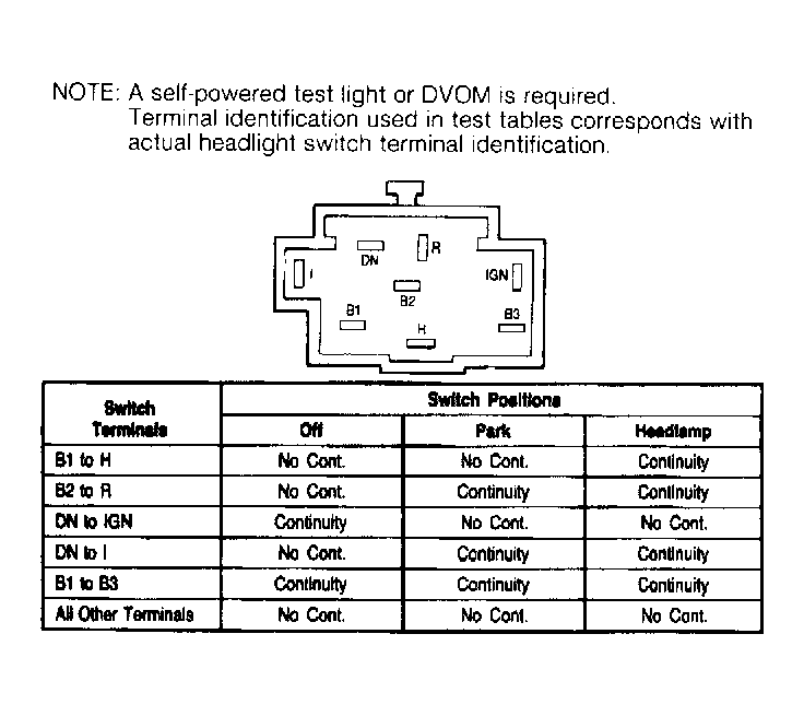 Courtesy of FORD MOTORS CO.