No Instrument Panel Illumination Test
- Check fuses No. 1, 2, 5 and 15. If any fuse(s) is blown, check circuit(s) for short(s) and repair as required. Refer to the WIRING DIAGRAMS
. If fuses are good, locate light module Black connector. Light module Black connector is located directly above and to the rear of fuse panel. See Fig 1
.
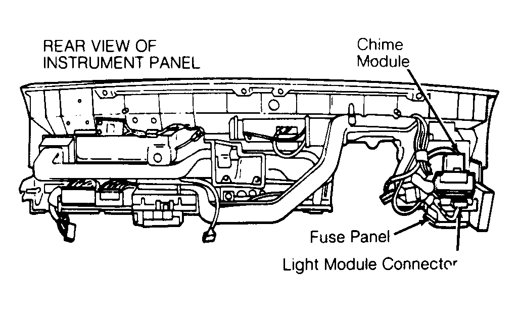 Courtesy of CHRYSLER MOTORS.
- Locate connector terminals C10 and C11. See Fig 2
. See LIGHT MODULE CONNECTOR TERMINAL ID
. Backprobe connector terminals using ohmmeter to check continuity of light module ground circuits from light module connector terminals C10 to ground, and C11 to ground. Repair as required. See WIRING DIAGRAMS
.
- Locate light module connector terminals D6 and D16. Turn ignition on. Using voltmeter with one lead grounded, check each terminal individually for battery voltage. If no voltage exists, repair wiring and retest. See WIRING DIAGRAMS
.
- If voltage exists at both connector terminals D6 and D16, locate light module connector terminals No. C7, C9 and D10. Place headlight switch in PARK or ON position, and set dimmer control to bright position. Check connector terminals No. C7, C9 and D10 to each have some amount of voltage. This will NOT be battery voltage. Voltage readings for each terminal will vary.
- If voltage exists at these terminals, go to step No. 7). If NO voltage exists at C7, check for open in Light Green/Red wiring circuit between light module and headlight switch. If voltage exists at C7 but DOES NOT exist at C9, replace light module and retest. If voltage exists at C9 but DOES NOT exist at D10, backprobe light module connector terminals C9 and D10 using a 3-amp fused jumper wire.
- If instrument panel now illuminates, light module is good. Check for open in wiring circuits between light module and headlight switch. See WIRING DIAGRAMS
. If wiring circuits are good, replace headlight switch. If instrument panel does not illuminate with jumper wire installed, replace light module and retest.
- If voltage exists at terminals C7, C9 and D10, check fuses No. 1 and 2 for voltage and check wiring circuits for opens between light module and headlight switch. Repair as required and retest.
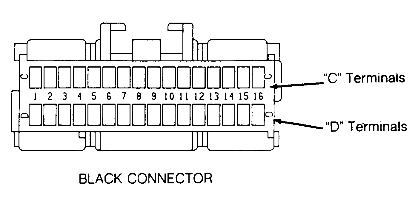 Courtesy of CHRYSLER MOTORS.
 LIGHT MODULE CONNECTOR TERMINAL ID
| Terminal |
Wire Color |
Circuit |
| C1 |
Light Green/Black |
High Beam Flash (Optical Horn) |
| C2 |
White/Light Green |
Headlight Dimmer |
| C3 |
Light Blue/Orange |
Right Turn Cancel |
| C4 |
Light Blue/Yellow |
Right Turn Signal |
| C5 |
Brown/Light Green |
Right Turn Signal |
| C6 |
Light Green/Yellow |
Headlight OFF |
| C7 |
Light Green/Red |
Parking Light Select |
| C8 |
Light Green/Orange |
Headlight Select |
| C9 |
Pink/Orange |
Dimmer Switch Power |
| C10 |
Black/Light Green |
Ground |
| C11 |
Black/Light Green |
Ground |
| C12 |
Light Green |
Left Turn Indicator |
| C13 |
Brown |
Right Turn Indicator |
| C14 |
Pink/White |
Left Turn Signal |
| C15 |
Pink/Black |
Right Turn Signal |
| C16 |
White/Yellow |
Left Turn Signal |
| D1 |
Violet/Tan |
Hazard Flasher |
| D2 |
Yellow/White |
Left Turn Cancel |
| D3 |
Light Blue/White |
Left Turn Signal |
| D4 |
Brown/Orange |
Left Turn Signal |
| D5 |
Gray |
Wiper Switch Panel Illumination |
| D6 |
Dark Green |
Fused Ignition Voltage |
| D7 |
Tan |
Instrument Panel Illumination |
| D8 |
Orange/Light Blue |
LCD Illumination |
| D9 |
White/Tan |
Stoplight Power Feed |
| D10 |
Light Blue/Light Green |
Instrument Panel Lights |
| D11 |
White/Orange |
Right Turn Signal |
| D12 |
Dark Blue/Red |
Chime Module |
| D13 |
Tan |
Parking Lights |
| D14 |
Pink |
High Beam Relay |
| D15 |
Light Green/Red |
Low Beam Relay |
| D16 |
Pink/White |
Power Input From |
| D5 |
Gray |
W Headlight CPU |