- Disconnect battery negative cable. Refer to Battery Negative Cable Disconnection and Connection
.
- Remove engine sight shield.
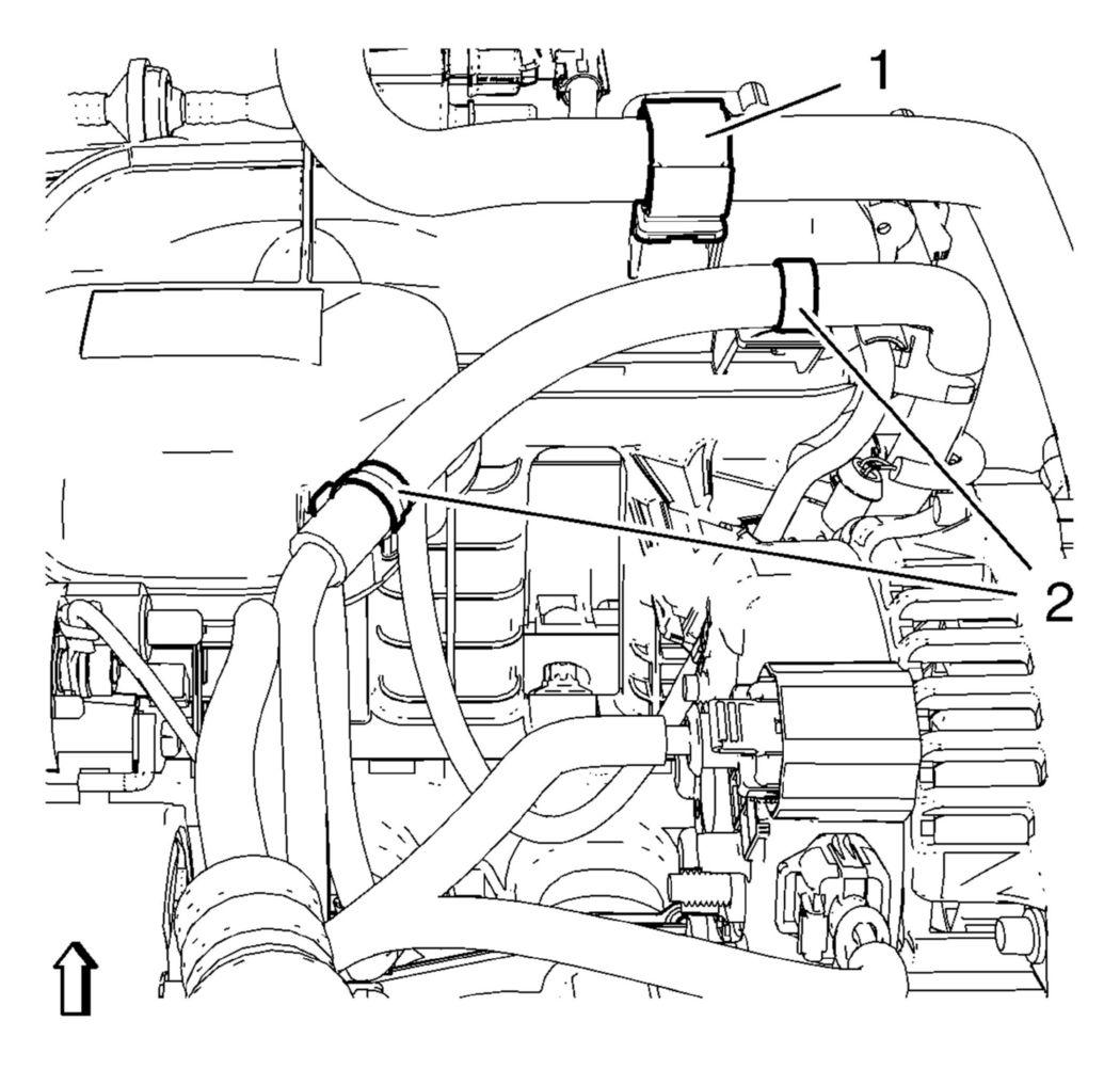
- Unclip the heater outlet hose from retainer clip (1).
 Courtesy of GENERAL MOTORS COMPANY
- Unclip the engine control module wiring harness from 2 retainer clips (2).
- Remove the charge air cooler outlet air hose from the throttle body. Refer to Charge Air Cooler Outlet Air Hose Replacement (Manual Transmission)
and Charge Air Cooler Outlet Air Hose Replacement (Automatic Transmission)
.
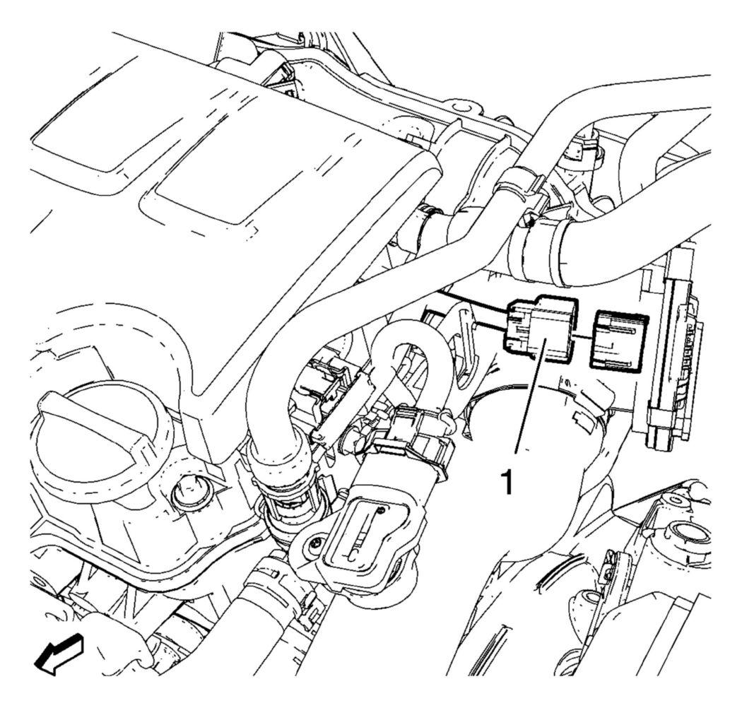
- Disconnect the throttle body wiring harness plug (1).
 Courtesy of GENERAL MOTORS COMPANY
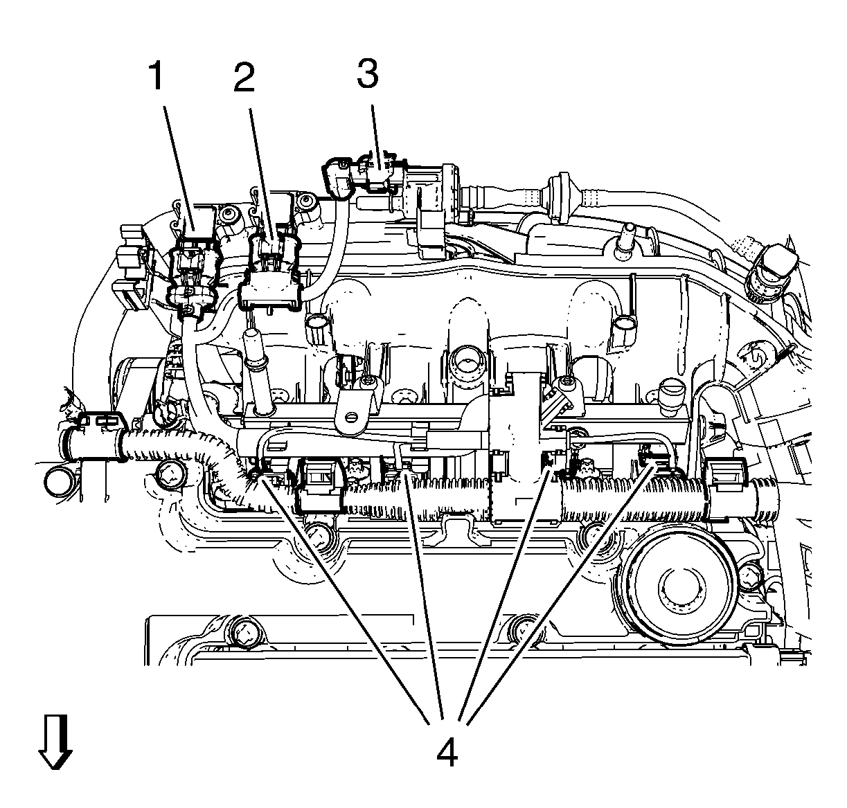
- Disconnect the evaporative emission canister purge solenoid valve wiring harness plug (3).
 Courtesy of GENERAL MOTORS COMPANY
- Disconnect the 2 manifold absolute pressure sensor wiring harness plugs (1) and (2).
NOTE:
Make note of the installed position of the manifold absolute pressure sensor wiring harness plugs to ensure they will be connected in their original position.
- Disconnect the 4 fuel injector wiring harness plugs (4).
- Unclip the engine control module wiring harness from the camshaft cover.
- Disconnect the turbocharger wastegate regulator solenoid valve wiring harness plug (3).
 Courtesy of GENERAL MOTORS COMPANY
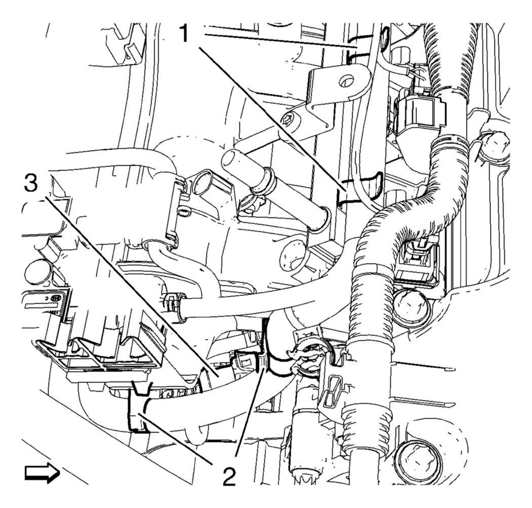
- Unclip the engine control module wiring harness from 2 intake manifold retainer clips (2) and from 2 fuel injection rail retainer clips (1).
- Remove fuel injector rail cap (1).
WARNING:
Gasoline or gasoline vapors are highly flammable. A fire could occur if an ignition source is present. Never drain or store gasoline or diesel fuel in an open container, due to the possibility of fire or explosion. Have a dry chemical (Class B) fire extinguisher nearby.
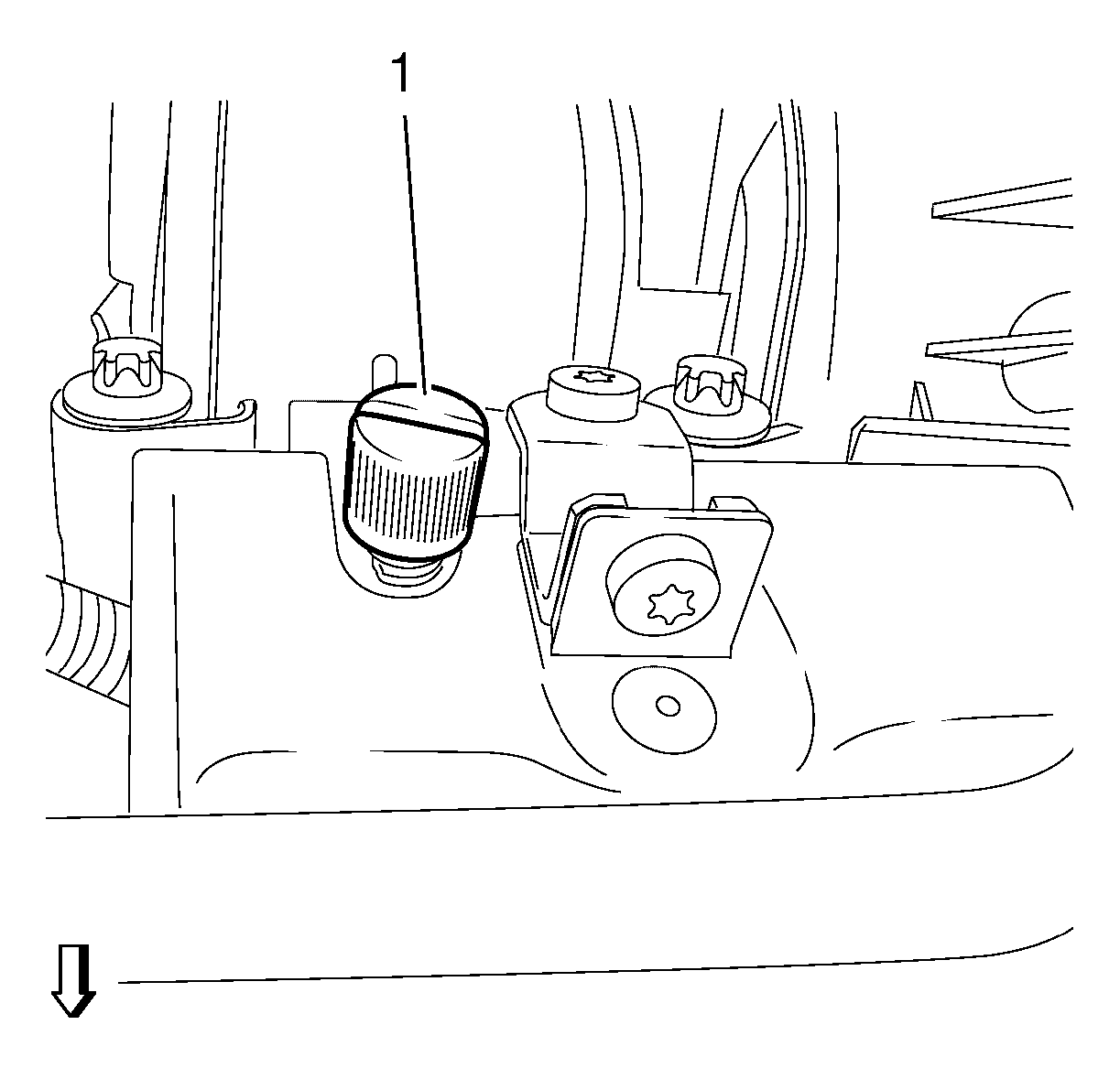 Courtesy of GENERAL MOTORS COMPANY
- Relieve the fuel system pressure. Use EN-34730-91
pressure tester (1).
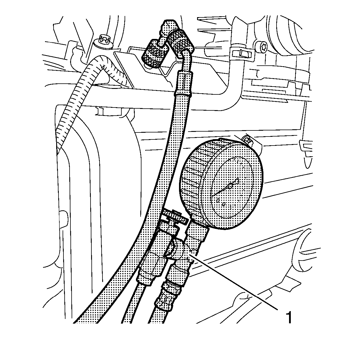 Courtesy of GENERAL MOTORS COMPANY
- Disconnect the fuel feed pipe (1) from the fuel rail. Refer to Metal Collar Quick Connect Fitting Service
.
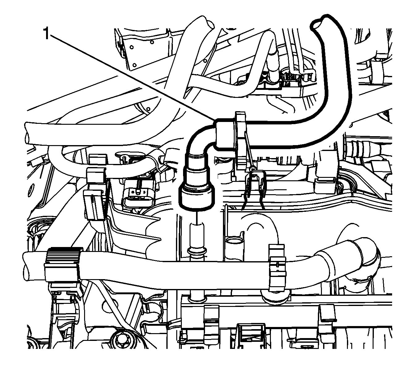 Courtesy of GENERAL MOTORS COMPANY
- Unclip fuel feed pipe from the retainer clip.
- Disconnect the positive crankcase ventilation pipe from the intake manifold. Refer to Positive Crankcase Ventilation Hose/Pipe/Tube Replacement
- Disconnect the fuel ventilation pipe (1) from the evaporative emission canister purge solenoid valve.
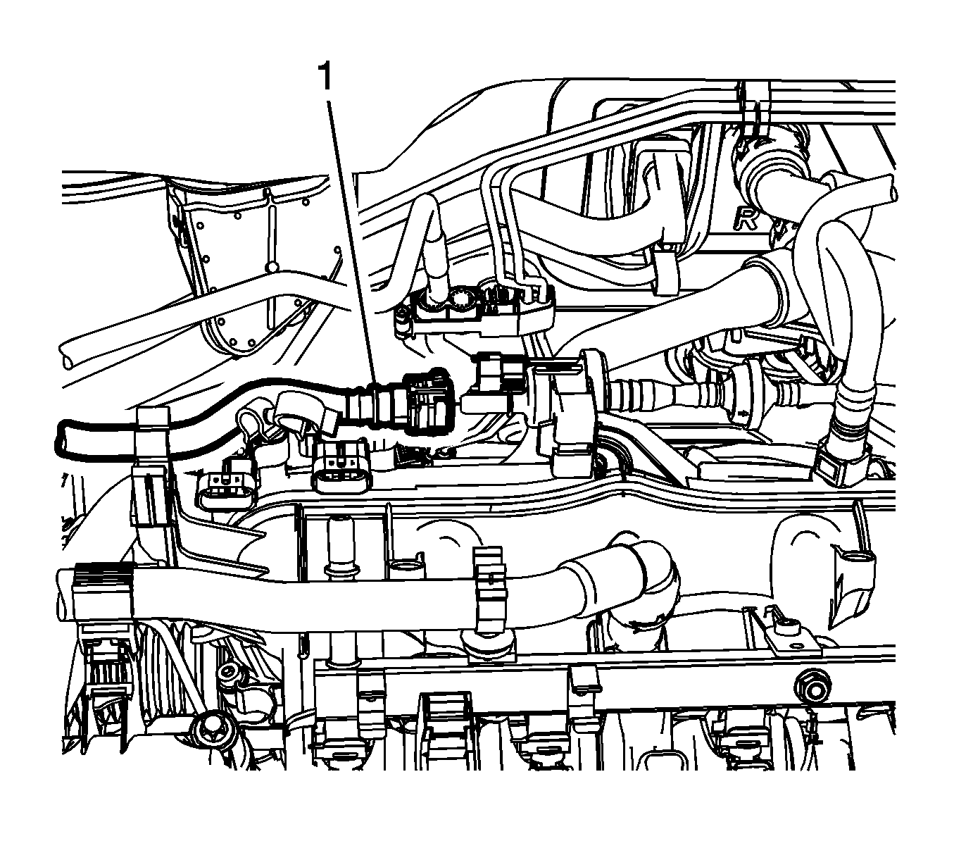 Courtesy of GENERAL MOTORS COMPANY
- Unclip the fuel ventilation pipe from the retainer clip.
- Disconnect the brake booster vacuum pipe (1) from intake manifold.
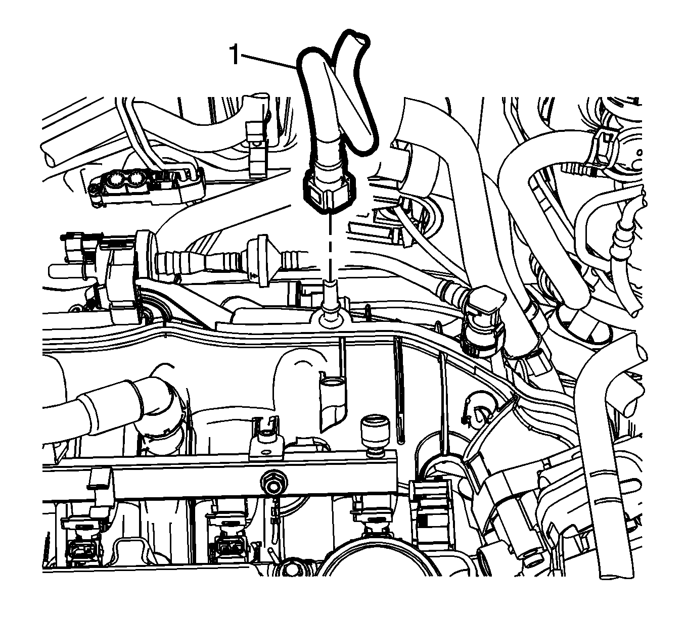 Courtesy of GENERAL MOTORS COMPANY
- Remove the 6 intake manifold bolts (1).
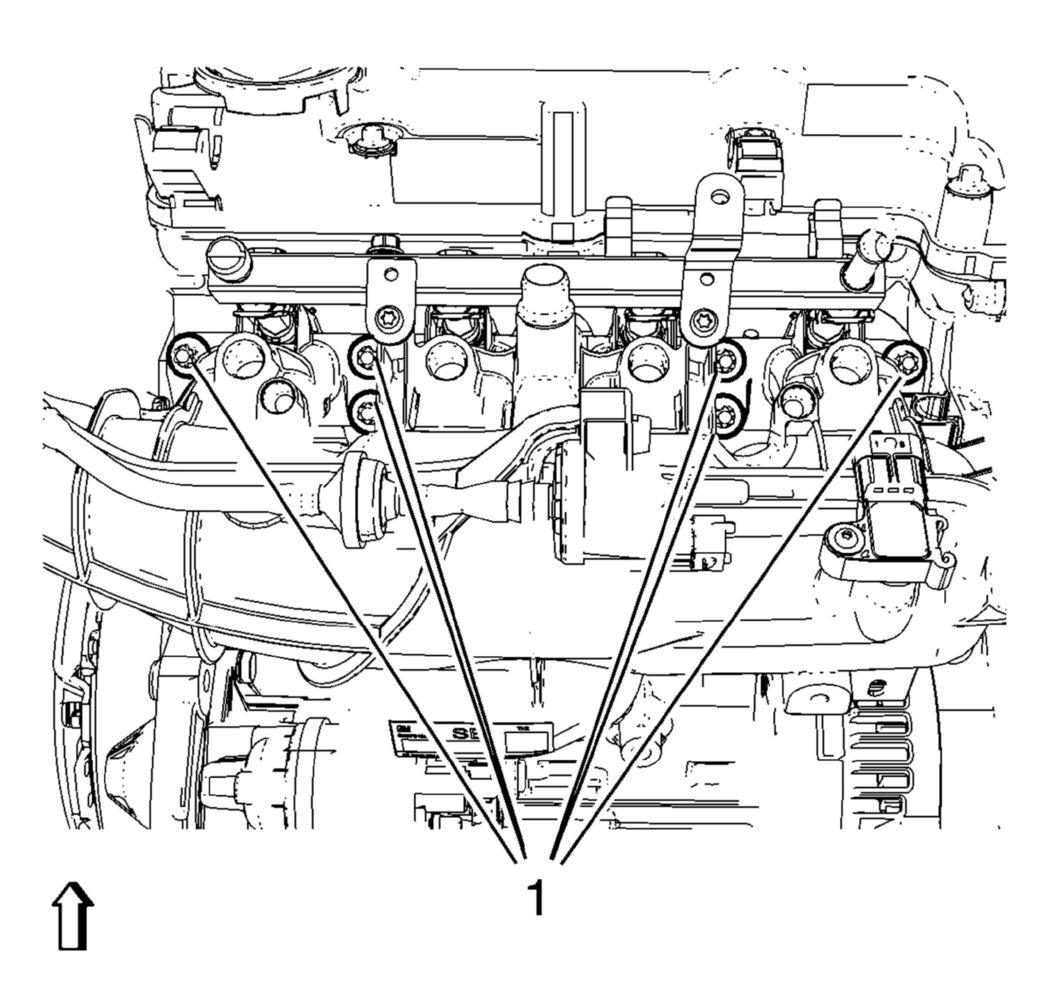 Courtesy of GENERAL MOTORS COMPANY
NOTE:
Intake manifold bolts remain in intake manifold. Note the installation of the fuel rail ground strap for proper installation.
- Remove the intake manifold (1).
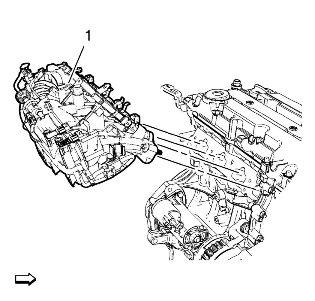 Courtesy of GENERAL MOTORS COMPANY
- Remove and DISCARD the intake manifold gasket.
- Remove the assembly parts from the intake manifold as necessary. Refer to Intake Manifold Disassemble .