Removal Procedure
- Remove the engine site shield. Refer to the following:
- Remove the air cleaner outlet duct. Refer to the following:
 Courtesy of GENERAL MOTORS CORP.
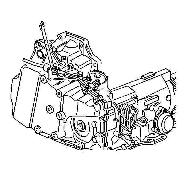
- Remove the transaxle shift cable from lever and bracket from the transaxle.
- Disconnect the transaxle wiring harness connector and disconnect the harness retainer from side cover stud.
- Remove the engine mount struts. Refer to the following:
 Courtesy of GENERAL MOTORS CORP.
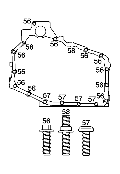
- Remove the top case side cover bolt (56, 58).
- Install the engine support fixture to support the engine/transaxle assembly. Refer to the following:
- Raise and support the vehicle. Refer to Lifting and Jacking the Vehicle
.
- Remove the left front wheel. Refer to Tire and Wheel Removal and Installation
.
- Remove the left front fender liner. Refer to Front Fender Liner Replacement
.
- Remove the wheel speed sensor harness from 4 retainers on the lower control arm.
- Remove the transmission mount-to-frame nuts. Refer to Transmission Mount Replacement - Left Side .
- Remove both stabilizer links and reposition stabilizer to access steering gear- to-frame bolts. Refer to Stabilizer Shaft Link Replacement
.
- Remove steering gear-to-frame bolts and support steering gear. Refer to Steering Gear Replacement
.
- Remove the front splash shield.
- Remove the positive battery cable center retainer at front frame rail.
- Remove the left side ball joint and support the left frame rail with a jack stand.
- Remove ONLY the left two frame-to-body bolts. DO NOT LOOSEN right side frame-to-body bolts. Refer to Frame Replacement
.
- Lower frame with a jackstand and remove jackstand.
- Position the drain pan under the transaxle.
- Remove the left drive axle from the transaxle. Refer to Wheel Drive Shaft Replacement
.
- Secure the drive axle to the strut assembly.
- Lower the vehicle.
- Using the engine support fixture lower the engine assembly to access the transaxle case side cover.
- Raise the vehicle.
 Courtesy of GENERAL MOTORS CORP.
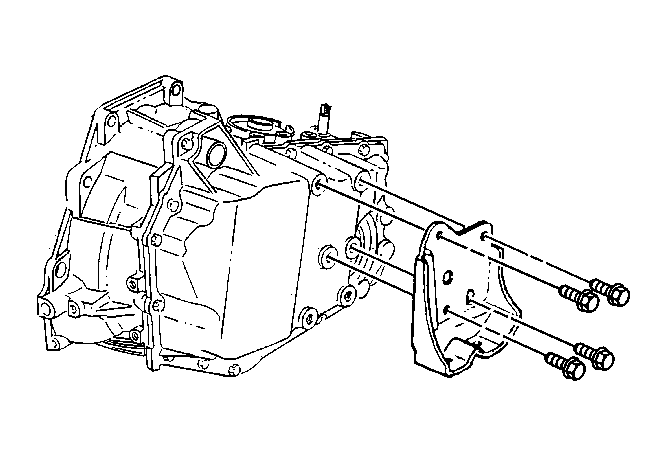
- Remove the transaxle mount bracket bolts and the bracket from the transaxle.
Courtesy of GENERAL MOTORS CORP.
- Remove the remaining case side cover bolts (56, 57, 58).
 Courtesy of GENERAL MOTORS CORP.
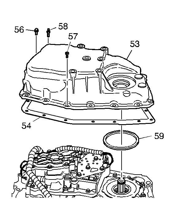
- Remove the case side cover (53).
- Remove the case side cover gasket (54).
- Remove the case side cover O-ring (59).
- Clean the side cover gasket mating surfaces.