Instrument Panel Removal Procedure
- Disconnect the negative battery cable. Refer to Battery Negative Cable Disconnect/Connect Procedure
in Charging System.
- Disable the SIR System. Refer to DISABLING SYSTEM
in SIR.
- Remove the front floor console. Refer to Console Replacement - Front Floor .
- Remove the IP compartment. Refer to Compartment Replacement - Instrument Panel (I/P) .
- Remove the IP steering column opening trim plate. Refer to Instrument Panel (I/P) Trim Panel Replacement - Left .
 Courtesy of GENERAL MOTORS CORP.
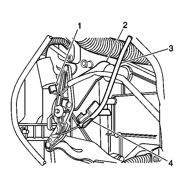
- Remove the mode control cable (3) from the heater case.
 Courtesy of GENERAL MOTORS CORP.
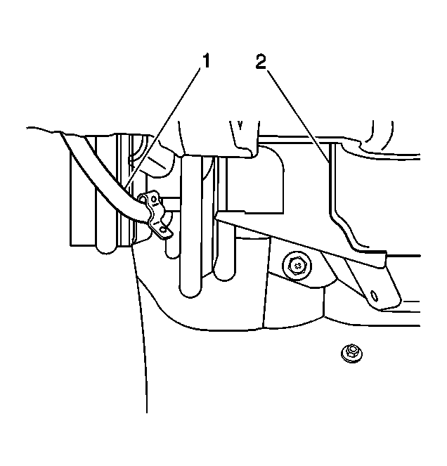
- Remove the temperature control cable (1) from the heater case (2).
 Courtesy of GENERAL MOTORS CORP.
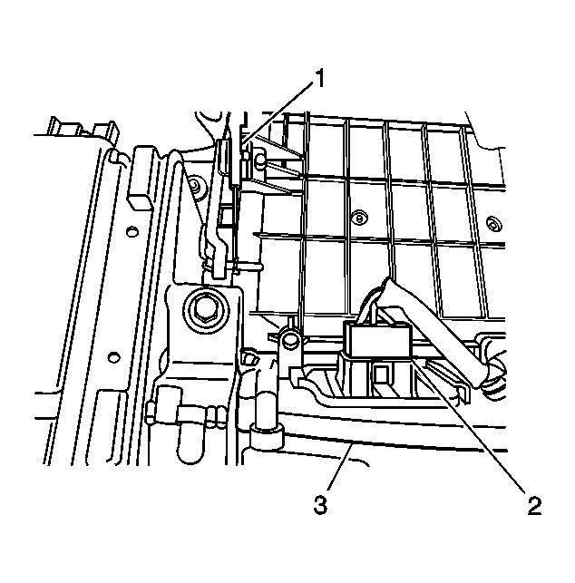
- Remove the fresh/recirc control cable (1) from the blower case (3).
- Remove the inflatable restraint IP module. Refer to SENSING & DIAGNOSTIC MODULE (SDM)
.
- Remove the steering column. Refer to STEERING COLUMN REPLACEMENT
.
 Courtesy of GENERAL MOTORS CORP.
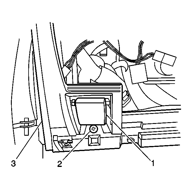
- Remove the screw (2) that retains the hood latch release handle (1) to the IP assembly (3).
- Position the hood latch release handle (1) aside in order to gain the necessary clearance to remove the IP assembly (3).
- Gently pry loose and remove the windshield side garnish moldings.
- Disconnect the 6 IP wiring harness electrical connectors from the junction block.
- Disconnect the radio antenna cable lead from the extension cable in the junction block area.
- Remove the connector position assurance (CPA) from the inflatable restraint sensing and diagnostic module (SDM) electrical connector.
- Disconnect the sensing and diagnostic module (SDM) electrical connector.
- Remove the bolt that retains the IP wiring harness ground wire. The bolt and the ground wire are located to the left front of the sensing and diagnostic module (SDM).
- Remove the ambient light sensor. Refer to DAYTIME RUNNING LAMPS (DRL) AMBIENT LIGHT SENSOR REPLACEMENT
.
 Courtesy of GENERAL MOTORS CORP.
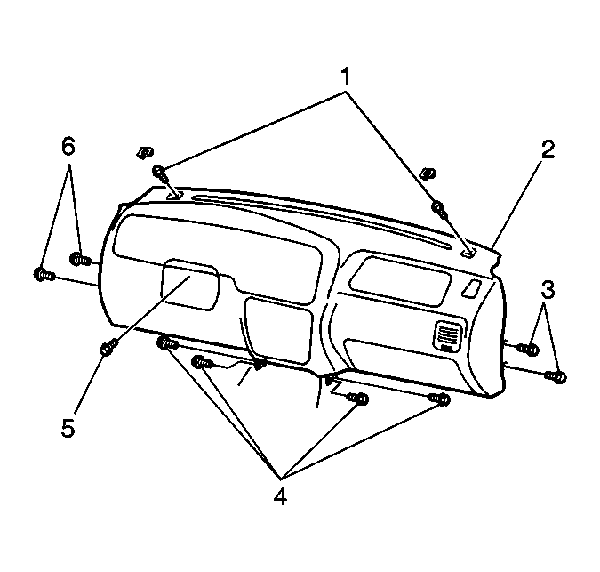
- Remove the 2 bolts (3, 6) at each side that retain the IP assembly (2).
- Fold back the floor panel carpet around the center of the IP assembly (2) in order to access the 2 center IP mounting bolts (4) at each side.
- Remove the 2 center IP mounting bolts (4) at each side that retain the IP assembly (2).
 Courtesy of GENERAL MOTORS CORP.
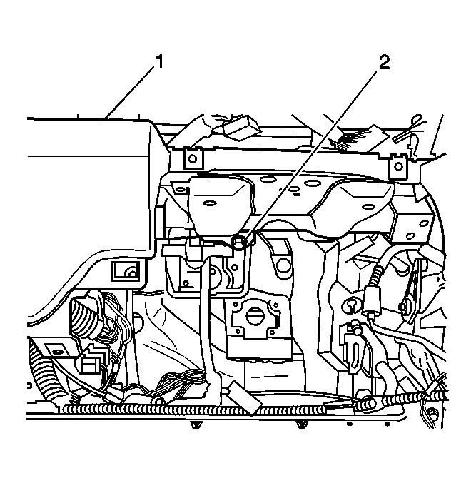
- Remove the bolt (2) that is located in the steering column area that retains the IP assembly (1).
 Courtesy of GENERAL MOTORS CORP.
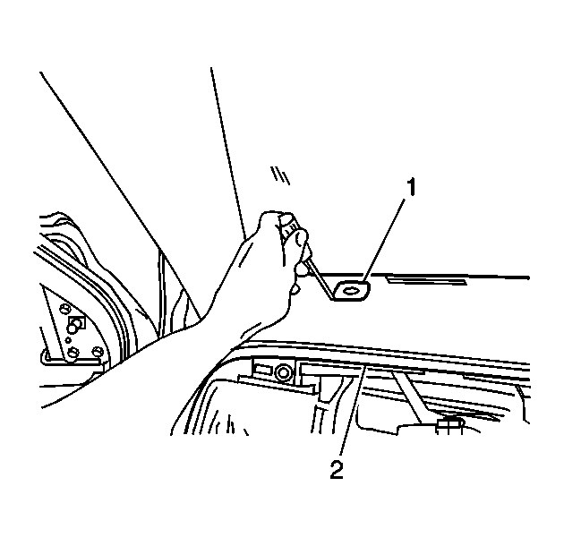
- Remove the left upper IP bolt trim cover (1) from the IP assembly (2).
 Courtesy of GENERAL MOTORS CORP.
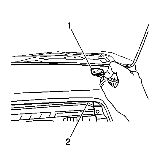
- Remove the right upper IP bolt trim cover (1) from the IP assembly (2).
Courtesy of GENERAL MOTORS CORP.
- Remove the 2 upper IP mounting bolts (1) that retain the IP assembly (2).
- Remove the IP assembly (2) from the vehicle.