Differential Carrier: Reassembly
- Using Output Shaft Bearing Installer (J-33788), install bearing into right sleeve. Using Bearing Installer (J-42211), install bearing into left sleeve. Install sleeves in into carrier. Thread sleeves in completely. Using Side Bearing Cup Installer (J-23423-A) and Driver Handle (J-8092), install side bearing cups into carrier.
- Place differential case assembly into carrier half that contains pinion gear. Using Side Bearing Adjusting Socket (J-42213), turn left sleeve in toward differential case until backlash is felt between ring and pinion gear. Assemble carrier halves. DO NOT use sealer. If carrier halves DO NOT contact completely, using Side Bearing Adjusting Socket (J-33792), back out right adjusting sleeve.
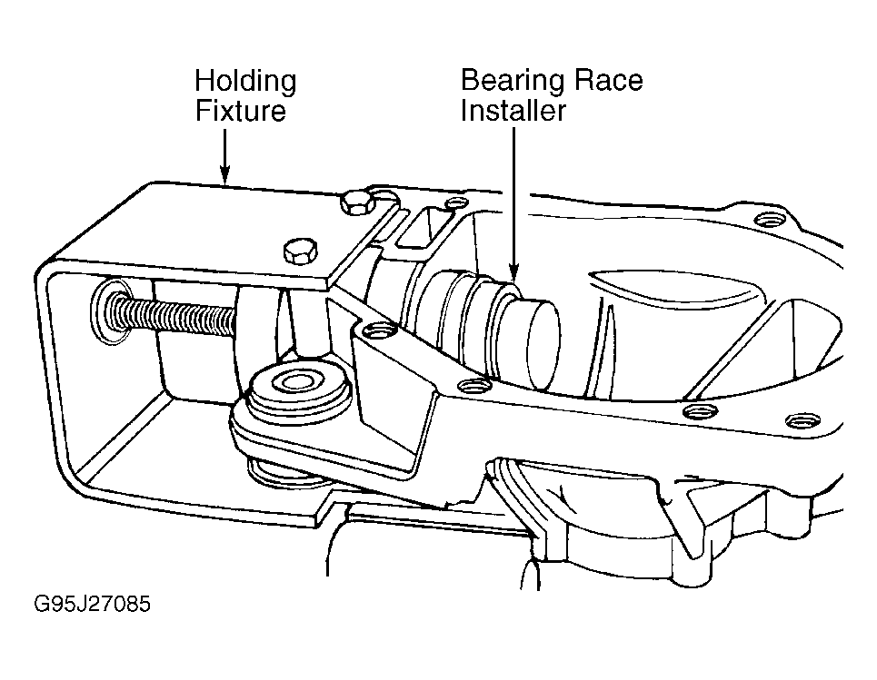
- Install pinion bearings using Holding Fixture (J-33837-1) and Bearing Race Installer (J-33837-4) until races are seated in carrier. See Fig 1. Lubricate right and outer bearings, then set pinion depth. See DRIVE PINION DEPTH under ADJUSTMENTS.
- Install appropriately sized shim onto pinion. Shim size was previously determined during pinion depth adjustment. Ensure bearing cups are installed. Using Pinion Bearing Installer (J-33785), install outer pinion bearing onto pinion. Install NEW collapsible spacer onto pinion shaft. Lubricate outer pinion bearing, and install inner pinion bearing and pinion seal into carrier case using Seal Installer (J-33782). Insert pinion, right bearing and collapsible spacer, into carrier case.
- Apply Sealer (GM P/N 12346004) to inside sealing surface of pinion yoke. Apply Seal Lubricant (GM P/N 12377985) to outside sealing surface of pinion yoke. Install pinion yoke in same position as marked during removal. Install drive pinion yoke by tapping it with a soft-face hammer until a few pinion shaft threads show through yoke. DO NOT hammer pinion yoke.
- Hold pinion in place from inside carrier half. Using Pinion Yoke Holder (J-8614), install NEW washer and NEW nut. Hold flange while slowly tightening nut and checking pinion flange until no end play is present. DO NOT tighten nut any further. Reference number of exposed threads on pinion stem recorded during removal.
- Rotate pinion several times to ensure bearings have been seated. Recheck end play. Set final pinion preload to 15-30 INCH lbs. (1.7-2.8 N.m) by tightening pinion nut in small increments, rotating pinion between increments. Each increment increases preload by several INCH lbs.
- If preload specification is exceeded, remove pinion and install NEW collapsible spacer. Once preload has been obtained, rotate pinion several times to ensure bearings have seated and recheck preload.
- Install side gears and thrust washers into differential case. If old side gears are being reinstalled, ensure they are placed in their original locations as marked during disassembly.
- Position one pinion gear between side gears and rotate gears until pinion gear is directly opposite opening in case. Place remaining pinion gear between side gears. Ensure holes in both pinion gears line up. Rotate pinion gears toward opening just enough to allow installation of thrust washers.
- Install differential pinion gear shaft. Install pinion gear shaft bolt. Install ring gear onto differential assembly. Tighten NEW bolts alternately in progressive steps to 59 ft. lbs. (80 N.m). Ring gear uses left-hand thread bolts.
- Press side bearings onto differential assembly using Side Bearing Installer (J-33790) and Driver Handle (J-8092).
- Using same side bearing adjusting socket used during disassembly, install sleeves into carrier case. Install side bearing races into carrier using Race Installer (J-23423-A). Place differential assembly into left carrier case half. Turn left sleeve inward until backlash is felt between ring and pinion.
- Remove carrier case from holding fixture, and attach carrier halves together using 4 bolts. If halves DO NOT make complete contact, using Side Bearing Adjusting Socket (J-33792), back out right sleeve. Install carrier case bolts and tighten to 37 ft. lbs. (50 N.m). Set ring gear backlash adjustment to specification. See RING GEAR BACKLASH under ADJUSTMENTS.
- Install side bearing adjusting sleeve lock tabs over left and right sleeves. Remove 4 bolts holding axle carrier halves together and separate carrier halves. Apply Sealant (GM 1052357) to one carrier housing surface.
- Reconnect axle carrier housing halves. Install 10 attaching bolts and tighten to specification. See TORQUE SPECIFICATIONS . Install drive seal into left side cover. Apply Sealant (GM P/N 1052357) to left side cover. Install 6 cover-to-carrier bolts securing left side cover and tighten to specification. See TORQUE SPECIFICATIONS .
- Install NEW pilot bearing into left output shaft using Pilot Bearing Installer (J-42211). Install shaft seal using Seal Installer (J-23911). Install shift housing seal using Shift Cable Housing Seal Installer (J-33799). Install NEW clutch shaft pilot bearing using Pilot Bearing Installer (J-33842). Install washer onto clutch shaft, and insert clutch shaft into carrier. Install clutch sleeve. Install thrust washer using grease. Align notch and tab as illustrated. See Figure. Install spring, shift shaft and fork.
- Install inner axle shaft to housing. Remove all oil and grease from axle shaft and carrier gasket surfaces. Apply Sealant (GM P/N 1052357) to carrier. Install shaft and housing assembly to carrier. Install 2 upper bolts finger-tight. Install remaining shift cable housing bolts. Install bushings using Bushing Remover/Installer (J-33791).
- Insert Hub Engagement Tool (J-33798) into shift fork. See Figure. Turn axle shaft while engaging and disengaging shift mechanism using hub engagement tool. Mechanism should operate smoothly. If mechanism does not operate smoothly, remove housing and inspect for damaged or improperly installed parts.
 Courtesy of GENERAL MOTORS CORP.