Test B: Chime Inoperative
- If preliminary procedure has not been performed, perform PRELIMINARY PROCEDURE
. If preliminary procedure has been performed, go to next step.
- If seat belt indicator operates, go to next step. If seat belt indicator does not operate, perform TEST X: SEAT BELT INDICATOR CIRCUIT MALFUNCTION
- Check turn signals for proper operation. If turn signals operate properly, go to next step. If turn signals do not operate properly, repair turn signal system as necessary. See appropriate EXTERIOR LIGHTS article in WIRING DIAGRAMS.
- Check headlights for proper operation. If headlights operate properly, go to next step. If headlights do not operate properly, repair headlight system as necessary. See appropriate HEADLIGHT SYSTEMS & DAYTIME RUNNING LIGHTS article in WIRING DIAGRAMS.
- Turn ignition switch to RUN position, with engine off. Ensure Rear Parking Assist (RPA) switch is in ON position. If RPA indicators turn on for 2 seconds and then turn off, go to step 11
. If RPA indicators do not turn on for 2 seconds and then turn off, repair RPA system as necessary. See appropriate PARKING ASSIST SYSTEMS article.
- Test Yellow wire between headlight switch and Daytime Running Lights (DRL) control module harness connector C2 terminal "F" for short to ground or short to voltage. See Fig 1
. DRL control module is located behind instrument panel, to right of steering column See Figure
. If no problem is found, go to next step. If problem is found, repair as necessary. After repair, go to step 17
.
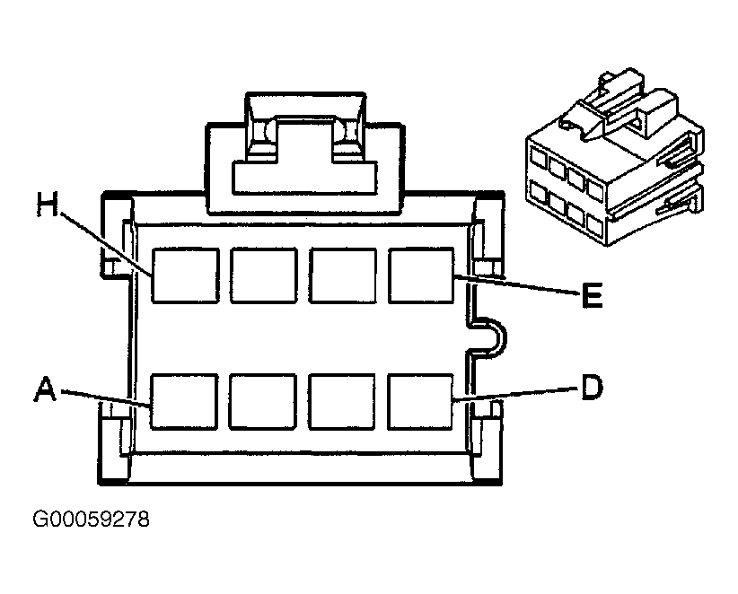 Courtesy of GENERAL MOTORS CORP.
- Insert key in ignition switch. Connect a test light between battery voltage and BCM harness connector C2 terminal D2 (Light Green wire). See Figure
. If test light illuminates, go to next step. If test light does not illuminate, go to step 12
.
- Open left front door. Connect a test light between battery voltage and BCM harness connector C2 terminal C7 (Light Blue wire). If test light does not illuminate, go to step 13
. If test light illuminates, go to step 14
.
- Test Light Green wire between BCM harness connector C2 terminal D2 and ignition key warning switch harness connector for an open or short to battery voltage. If not problem is found, go to step 16
. If problem is found, repair as necessary. After repair, go to step 17
.
- Test Light Blue wire between BCM harness connector C2 terminal C7 and left front door lock harness connector for an open or short to battery voltage. If problem is not found, go to step 15
. If problem is found, repair as necessary. After repair, go to step 17
.
- Check for poor connections at BCM harness connector C2. If no problem is found, go to step 6
. If problem is found, repair as necessary. After repair, go to step 17
.
- Check for poor connections at BCM harness connector C2 and ignition key warning switch harness connector. If no problem is found, go to step 9
. If problem is found, repair as necessary. After repair, go to step 17
.
- Check for poor connections at BCM harness connector C2 and left front door lock harness connector. If no problem is found, go to step 10
. If problem is found, repair as necessary. After repair, go to step 17
.
- Replace BCM. See BODY CONTROL MODULE
under REMOVAL & INSTALLATION. After repair, go to step 17
.
- Replace left front door lock. See appropriate POWER DOOR LOCKS & REMOTE KEYLESS ENTRY SYSTEMS article. After repair, go to step 17
.
- Replace ignition key alarm switch. See appropriate STEERING COLUMN SWITCHES article. After repair, go to next step.
- Operate system to verify repair. If system does not operate properly, go to step 2
. If system operates properly, system is okay.