Test A: Chime Always On
- If preliminary procedure has not been performed, PRELIMINARY PROCEDURE
. If preliminary procedure has been performed, go to next step.
- If Rear Parking Assist (RPA) indicators are not on, go to next step. If RPA indicators are on, repair RPA system as necessary. See appropriate PARKING ASSIST SYSTEMS article.
- If no other indicators are on, go to next step. If any other indicators are on, repair by symptom. See SYMPTOM INDEX
table under SYMPTOM INDEX.
- Test Light Green wire between Instrument Panel Cluster (IPC) harness connector C1 terminal "L" and Body Control Module (BCM) harness connector C2 terminal D3 for short to ground. See Figure
and Fig 1
. If no problem is found, go to step 10
. If problem is found, repair as necessary. After repair, go to stop 16
.
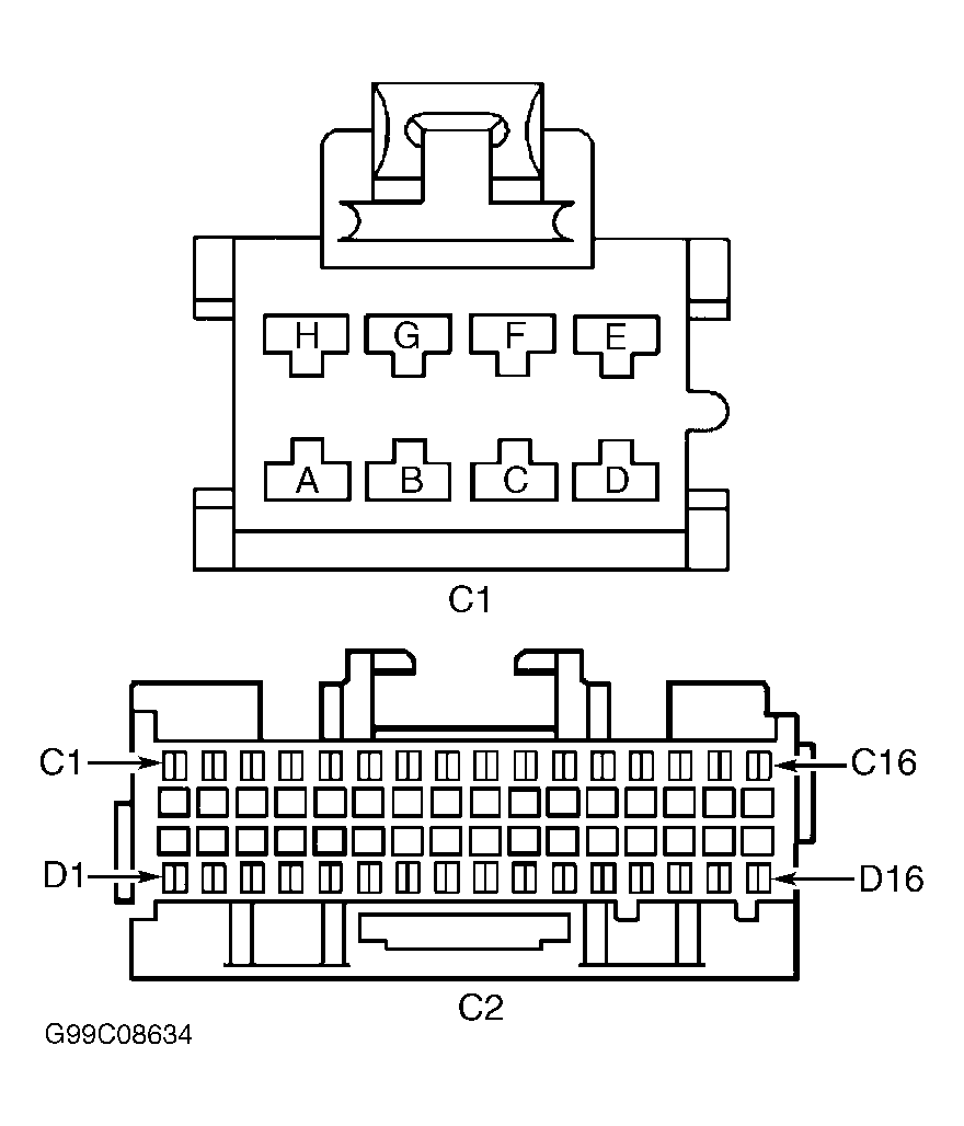 Courtesy of GENERAL MOTORS CORP.
- Turn ignition switch to OFF position. Ensure headlight and IPC light dimmer switch is in OFF position. Disconnect BCM harness connector C2. Connect a test lamp between ground and BCM harness connector C2 terminal C2 (White wire). If test light illuminates, go to next step. If test light does not illuminate, go to step 8
.
- Disable air bag system. See SERVICE PRECAUTIONS and DISABLING & ACTIVATING AIR BAG SYSTEM in appropriate AIR BAG RESTRAINT SYSTEMS article. Connect a test light between battery voltage and BCM harness connector C2 terminal D2 (Light Green wire). See Fig 1
. If test light illuminates, go to next step. If test light does not illuminate, go to step 14
.
- Remove ignition key from ignition switch. Connect a test lamp between battery voltage and BCM harness connector C2 terminal D2 (Light Green wire). If test light illuminates, leave test light connected and go to step 9
. If test light does not illuminate, go to step 14
.
- Test White wire between BCM harness connector C2 terminal C2 and headlight and IPC light dimmer switch harness connector terminal "B" for an open. See Fig 1
and Fig 2
. If no problem is found, go to step 13
. If problem is found, repair as necessary. After repair, go to step 16
.
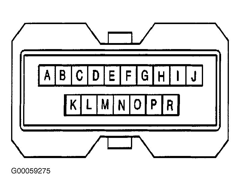 Courtesy of GENERAL MOTORS CORP.
- Disconnect in-line connector C201. In-line connector C201 is mounted to left side of steering column, near base. See Figure
. If test light remains illuminated, go to step 12
. If test light turns off, go to step 15
.
- Check for poor connections at headlight and IPC light dimmer switch harness connector. If no problem is found, go to next step. If problem is found, repair as necessary. After repair, go to step 16
.
- Check for poor connections at BCM harness connector C2. If no problem is found, go to step 5
. If problem is found, repair as necessary. After repair, go to step 16
.
- Repair short to ground in Light Green wire between BCM harness connector C2 terminal D2 and ignition key alarm switch. Ignition key alarm switch is part of ignition lock module assembly in steering column. See Figure
. After repair, go to step 16
.
- Replace headlight and IPC dimmer switch. See HEADLIGHT & INSTRUMENT PANEL CLUSTER DIMMER SWITCH
under REMOVAL & INSTALLATION. After repair, go to step 16
.
- Replace BCM. See BODY CONTROL MODULE
under REMOVAL & INSTALLATION. After repair, go to step 16
.
- Replace ignition key alarm switch. See appropriate STEERING COLUMN SWITCHES article. After repair, go to next step.
- Operate system to verify repair. If system does not operate properly, go to step 2
. If system operates properly, system is okay.