DTC P0462: Fuel Level Signal Low: Testing
- If IPC diagnostic system check has not been performed, perform INSTRUMENT PANEL CLUSTER DIAGNOSTIC SYSTEM CHECK
under SELF-DIAGNOSTIC SYSTEM. If IPC diagnostic system check has been performed, go to next step.
- Turn ignition switch to OFF position. Connect scan tool to Data Link Connector (DLC). DLC is located below left side of instrument panel, to right of steering column. See Figure
. Turn ignition switch to RUN position, with engine off. Using scan tool, observe FUEL LEVEL parameter in PCM EVAP DATA LIST. If scan tool displays parameter is less than 3.5 percent, go to next step. If scan tool does not display parameter is less than 3.5 percent, see DIAGNOSTIC AIDS
.
- Turn ignition switch to OFF position. Disconnect in-line connector C305. In-line connector C305 is a Gray 12-pin Male connector connected to a Gray 4-pin Female connector and a Natural 8-pin Female connector. Connector C305 is located in body wiring harness, mounted as a pass-through under vehicle, behind back seat. See Figure
. Turn ignition switch to RUN position, with engine off. Using scan tool, observe FUEL LEVEL parameter in PCM EVAP DATA LIST. If scan tool does not display parameter is more than 3.5 percent, go to next step. If scan tool displays parameter is more than 3.5 percent, go to step 5
.
- Test Purple wire between in-line Gray 12-pin connector C305 terminal No. 3D and PCM Clear harness connector C2 terminal No. 69 for short to ground. See Fig 1
and Fig 2
. If no problem is found, go to step 7
. If problem is found, repair as necessary. After repair, go to step 10
.
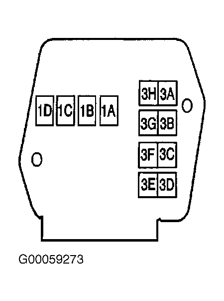 Courtesy of GENERAL MOTORS CORP.
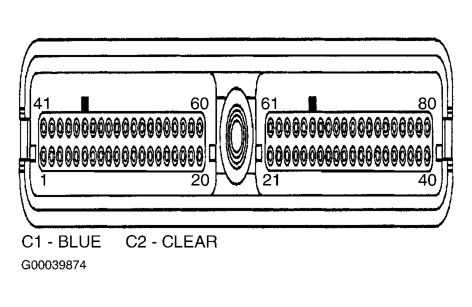 Courtesy of GENERAL MOTORS CORP.
- Test Purple wire between fuel level sensor harness connector and in-line Natural 8-pin connector C305 terminal "D" for short to ground. See Fig 3
. If no problem is found, go to step 7
. If problem is found, repair as necessary. After repair, go to step 10
.
- Check for poor connections at fuel level sensor harness connector. If no problem is found, go to step 8
. If problem is found, repair as necessary. After repair, go to step 10
.
- Check for poor connections at PCM harness connector C2. If no problem is found, go to step 9
. If problem is found, repair as necessary. After repair, go to step 10
.
- Replace fuel level sensor. See. FUEL LEVEL SENSOR
under REMOVAL & INSTALLATION. After repair, go to step 10
.
- Replace PCM. See POWERTRAIN CONTROL MODULE
under REMOVAL & INSTALLATION. After repair, go to next step.
- Using scan tool, clear DTCs. Operate vehicle under CODE ENABLE CRITERIA
conditions. If DTC resets, go to step 2
. If DTC does not reset, system is okay.