Test K: Chime Inoperative
- If audible warnings system operation check has been performed, go to next step. If audible warnings system operation check has not been performed, perform audible warnings system operation check. See AUDIBLE WARNINGS SYSTEM OPERATION CHECK
under TROUBLE SHOOTING.
- Disconnect chime audio alarm module 7-pin harness connector. Turn ignition switch to RUN position. Measure resistance between ground and chime audio alarm module harness connector terminal No. 7 (Black wire). See Figure
. If resistance is 2 ohms or more, go to next step. If resistance is less than 2 ohms, go to step 4
.
- Measure resistance between ground and junction block harness connector C4 by backprobing terminal No. 16 (Black wire). See Fig 1
. If resistance is 2 ohms or more, go to step 5
. If resistance is less than 2 ohms, go to step 6
.
- Measure voltage between ground and chime audio alarm module harness connector terminal No. 5 (Black/White wire). See Figure
. If battery voltage does not exist, go to step 7
. If battery voltage exists, go to step 8
.
- Inspect junction block case ground for corrosion. If junction block case ground is okay, replace junction block. After repair, perform AUDIBLE WARNINGS SYSTEM OPERATION CHECK
under TROUBLE SHOOTING.
- Repair open in Black wire between junction block and chime audio alarm module. After repair, perform AUDIBLE WARNINGS SYSTEM OPERATION CHECK
under TROUBLE SHOOTING.
- Repair open Black/White wire between chime audio alarm module and junction block. After repair, perform AUDIBLE WARNINGS SYSTEM OPERATION CHECK
under TROUBLE SHOOTING.
- Replace chime audio alarm module. After repair, perform AUDIBLE WARNINGS SYSTEM OPERATION CHECK
under TROUBLE SHOOTING.
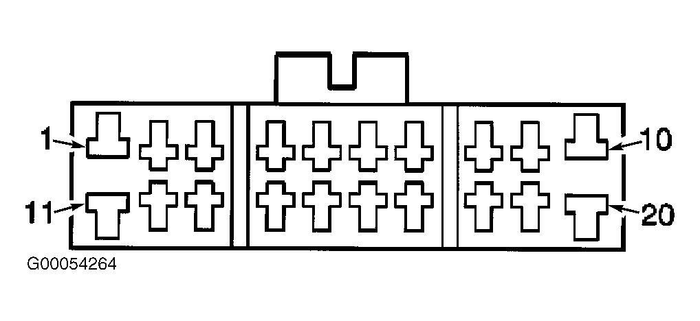 Courtesy of GENERAL MOTORS CORP.