DTC B2965: Key In Ignition Fault: Testing
- If audible warning system diagnostic system check has been performed, go to next step. If audible warning system diagnostic system check has not been performed, go to AUDIBLE WARNING SYSTEM DIAGNOSTIC SYSTEM CHECK under SELF-DIAGNOSTIC SYSTEM.
- Connect scan tool to Data Link Connector (DLC). DLC is located at lower left side of instrument panel, near steering column. Turn ignition switch to RUN position. Using scan tool, observe KEY IN IGNITION input on Body Control Module (BCM) data list. If scan tool does not indicate ACTIVE, go to next step. If scan tool indicates ACTIVE, perform this step while wiggling related wiring and connectors. This can often cause malfunction to appear.
- Turn ignition switch to LOCK position. Disconnect BCM 24-pin Brown harness connector C3. BCM is located behind left side of instrument panel. Connect test light between battery positive terminal and BCM harness connector C3 terminal B12 (Light Green wire). See Fig 1. If test light does not illuminate, go to next step. If test light illuminates, go to step 7.
- Disconnect ignition switch 6-pin harness connectors C1 and C2, located on right side of steering column. Check for open, high resistance or short to ground in Light Green wire between BCM harness connector C3 terminal B12 and ignition switch harness connector C2 terminal "F". See Fig 1 and Fig 2
. If problem is not found, go to next step. If problem is found, repair Light Green wire as necessary. After repairs, go to step 10.
- Check for open or high resistance in Black wire between ground and ignition switch harness connector C1 terminal "F". See Fig 3. If problem is not found, go to next step. If problem is found, repair Black wire as necessary. Ground point is located behind left side of instrument panel. After repairs, go to step 10.
- Check for poor connections at ignition switch harness connectors C1 and C2. If problem is not found, go to step 8. If problem is found, repair as necessary. After repairs, go to step 10.
- Check for poor connections at BCM harness connector C3. If problem is not found, go to step 9. If problem is found, repair as necessary. After repairs, go to step 10.
- Replace ignition switch. See STEERING COLUMN SWITCHES
article. For 2002, see STEERING COLUMN SWITCHES
article. After repairs, go to step 10.
- Replace BCM. See BODY CONTROL MODULE under REMOVAL & INSTALLATION. Program BCM. See BODY CONTROL MODULE PROGRAMMING/REGULAR PRODUCTION OPTION CONFIGURATION under PROGRAMMING. After repairs, go to next step.
- Using scan tool, clear DTCs. Turn ignition switch to LOCK position. Wait 30 seconds. Turn ignition switch to RUN position. Retrieve DTCs. If DTC B2965 is retrieved, go to step 2. If DTC B2965 is not retrieved, system is okay at this time.
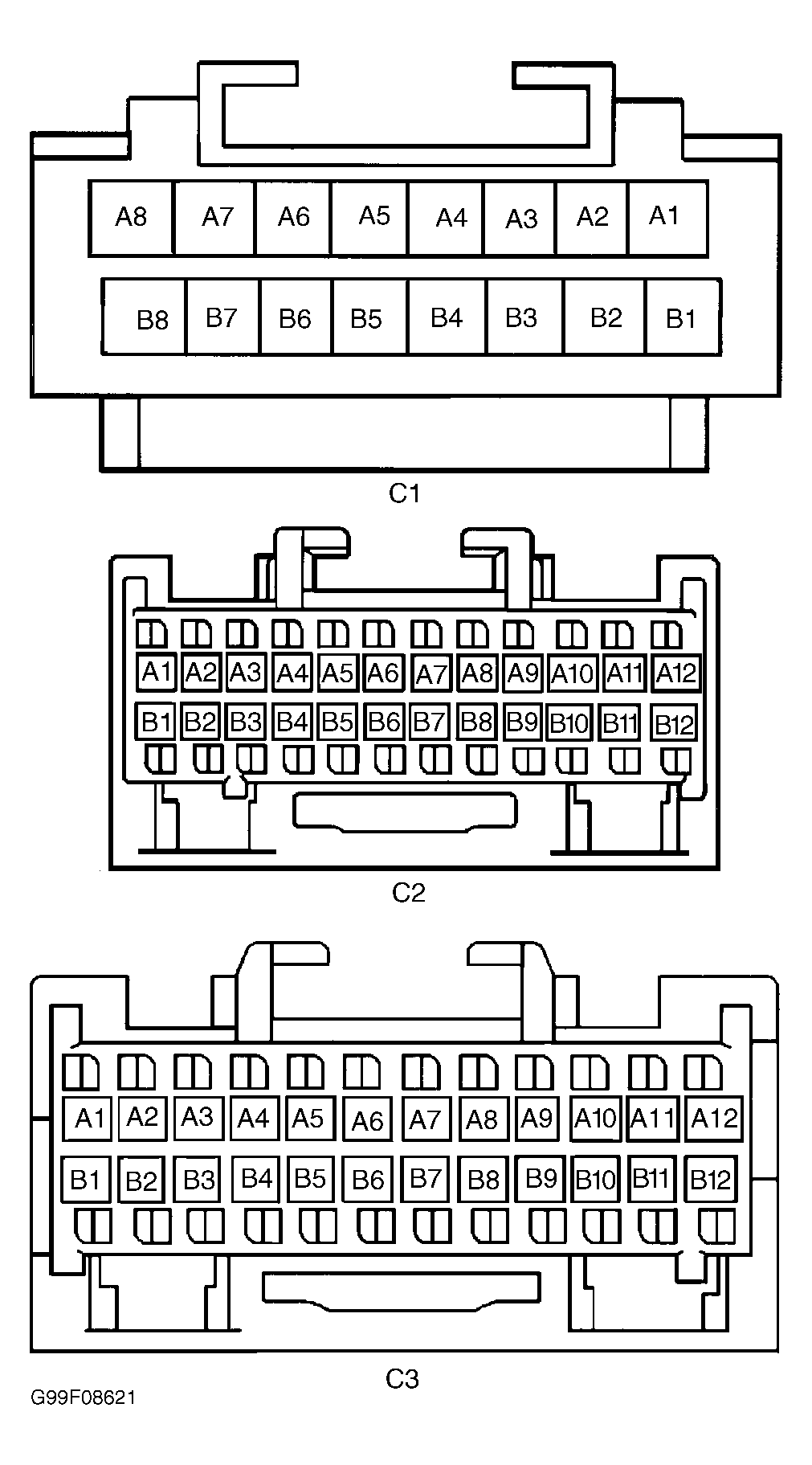 Courtesy of GENERAL MOTORS CORP.
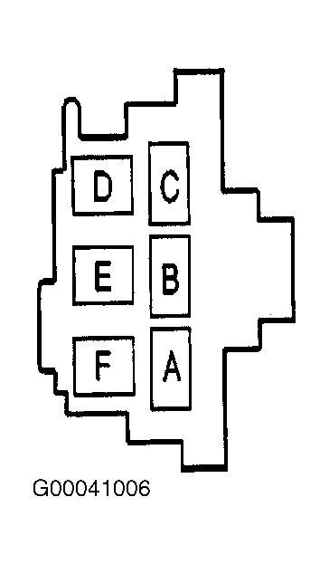 Courtesy of GENERAL MOTORS CORP.
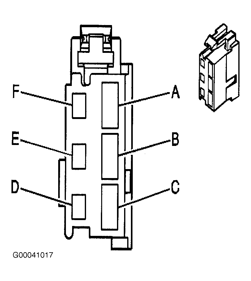 Courtesy of GENERAL MOTORS CORP.