Test G: Theft Deterrent Shock Sensor Inoperative: Testing
- If theft deterrent diagnostic system check has been performed, go to next step. If theft deterrent diagnostic system check has not been performed, perform diagnostic system check before proceeding. See THEFT DETERRENT DIAGNOSTIC SYSTEM CHECK under SELF-DIAGNOSTIC SYSTEM.
- Arm Content Theft Deterrent (CTD) system. See CONTENT THEFT DETERRENT SYSTEM under DESCRIPTION & OPERATION. Locate and tap on shock sensor. If alarm does not trigger, go to next step. If alarm is triggered, inspect for intermittents or poor connections. See TROUBLE SHOOTING .
- Enter Body Control Module (BCM) diagnostic system check. See USING SECURITY INDICATOR under RETRIEVING BODY CONTROL MODULE DIAGNOSTIC TROUBLE CODES. Locate and tap on shock sensor while in diagnostic mode. If chime sounds when shock sensor is tapped, go to next step. If chime does not sound when shock sensor is tapped, go to step 5.
- Adjust shock sensor. See SHOCK SENSOR under ADJUSTMENTS. Go to step 20.
- Disconnect shock sensor 4-pin harness connector. Connect a test light between ground and shock sensor harness connector terminal "A" (Orange wire). See Fig 1. If test light does not illuminate, go to next step. If test light illuminates, go to step 9.
- Connect a test light between ground and shock sensor harness connector terminal "C" (Black wire). If test light does not illuminate, go to next step. If test light illuminates, go to step 8.
- Repair open in Orange wire between shock sensor and instrument panel fuse block. Instrument panel fuse block is located behind left side of instrument panel. Go to step 20.
- Repair open in Black wire between shock sensor and ground. Ground point is located behind left kick panel, near "A" pillar. Go to step 20.
- Connect a test light between ground and shock sensor harness connector terminal "D" (Light Blue wire). See Fig 1. If chime sounds when test light is connected (horn may sound), go to next step. If chime does not sound when test light is connected (horn may sound), go to step 16.
- Connect a test light between ground and shock sensor harness connector terminal "B" (Light Green wire). If chime sounds when test light is connected (horn may sound), go to next step. If chime does not sound when test light is connected (horn may sound), go to step 13.
- Inspect shock sensor harness connector for poor connections. If poor connections are not found, go to next step. If poor connections are found, repair as necessary then go to step 20.
- Replace shock sensor, then go to step 20.
- Disconnect BCM 32-pin harness connector C3. BCM is located behind right side of instrument panel, near blower motor. See Figure. Connect a test light between ground and BCM harness connector C3 terminal D14 (Light Green wire). See Figure. If chime sounds when test light is connected (horn may sound), go to next step. If chime does not sound when test light is connected (horn may sound), go to step 15.
- Repair open in Light Green wire between shock sensor and BCM. Go to step 20.
- Inspect for a poor connection between ground and BCM harness connector C3 terminal D14 (Light Green wire). If a poor connection is not found, go to step 19. If a poor connection is found, repair as necessary then go to step 20.
- Disconnect BCM 32-pin harness connector C3. BCM is located behind right side of instrument panel, near blower motor. See Figure. Connect a test light between ground and BCM harness connector C3 terminal D2 (Light Blue wire). See Figure. If chime sounds when test light is connected (horn may sound), go to next step. If chime does not sound when test light is connected (horn may sound), go to step 18.
- Repair open in Light Blue wire between shock sensor and BCM. Go to step 20.
- Inspect for a poor connection between ground and BCM harness connector C3 terminal D2 (Light Blue wire). If a poor connection is not found, go to next step. If a poor connection is found, repair as necessary then go to step 20.
- Replace BCM. See BODY CONTROL MODULE under PROGRAMMING. After replacement, go to next step.
- Operate system to verify repair. If system is not operating correctly, repeat test beginning at step 3.
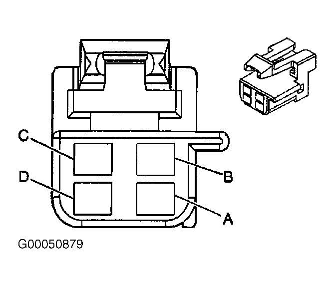 Courtesy of GENERAL MOTORS CORP.