All Shift Select Buttons Do Not Light
- If this diagnostic was referred from another test, go to next step. If diagnostic started here, see FUNCTION TEST under DIAGNOSIS & TESTING.
- In instrument panel fuse block, check condition of ILLUM fuse No. 5 (10-amp) and 4WD fuse No. 15 (10-amp) for open. Also check ATC fuse (20-amp) in Underhood Bussed Electrical Center (UBEC), if equipped. If any fuse is open, go to next step. If no fuses are open, see ALL SHIFT SELECT BUTTONS REMAIN LIT .
- Replace failed fuse(s). Turn ignition on (engine off). Check operation of electronic shift system. Recheck fuse for open. If fuse failed again, go to next step. If fuse is okay, see FUNCTION TEST under DIAGNOSIS & TESTING.
- Turn ignition off. Check Gray wire and Brown wire at select switch for short to ground if fuse No. 5 or No. 15 was open. If ATC fuse was open, check Orange wire at TCCM for short to ground. If any circuit is shorted to ground, go to next step. If all circuits are not shorted to ground, go to step 6.
- With ignition off, repair grounded circuit noted in previous step. Replace open fuse, then go to FUNCTION TEST under DIAGNOSIS & TESTING.
- Check pin "A" (Gray/Black wire) on back of shift select switch for battery voltage. If battery voltage is present, go to step 8. If battery voltage is not present, go to next step. See Fig 1.
- If an open exists in Gray wire or Brown wire between fuse and transfer case select switch connector, repair open. Check for loose electrical connections in circuit. When repair is complete, see FUNCTION TEST under DIAGNOSIS & TESTING.
- Turn ignition on (engine off). Ensure shift select switch connector is properly connected. Depress all 3 shift select buttons while checking each of the following terminals for battery voltage: Pin "A", pin "B" and pin "F". See Fig 2. See WIRING DIAGRAMS . If battery voltage is present, go to next step. If battery voltage is not present, go to step 10.
- Turn ignition off. Check for proper ground in Black wire circuits of TCCM connector. If wires are properly grounded, go to step 12. If wires are not properly grounded, go to step 11.
- Ensure ignition is off. Replace shift select switch. After replacement, see FUNCTION TEST under DIAGNOSIS & TESTING.
- If an open exists in Black wire circuit from TCCM connector to ground, repair open as necessary, then go to FUNCTION TEST under DIAGNOSIS & TESTING.
- Check TCCM connector, terminal C6 (Orange wire) and terminal C8, (Brown wire) battery voltage. See Fig 2. See WIRING DIAGRAMS for terminal identification. If battery voltage is present at both pins, diagnose TCCM. See RETRIEVING CODES under DIAGNOSIS & TESTING. If battery voltage is not present at both pins, go to next step.
- If battery voltage does not exist, an open exists in either circuit in previous step between fuse and TCCM connector. Repair open, then go to FUNCTION TEST under DIAGNOSIS & TESTING.
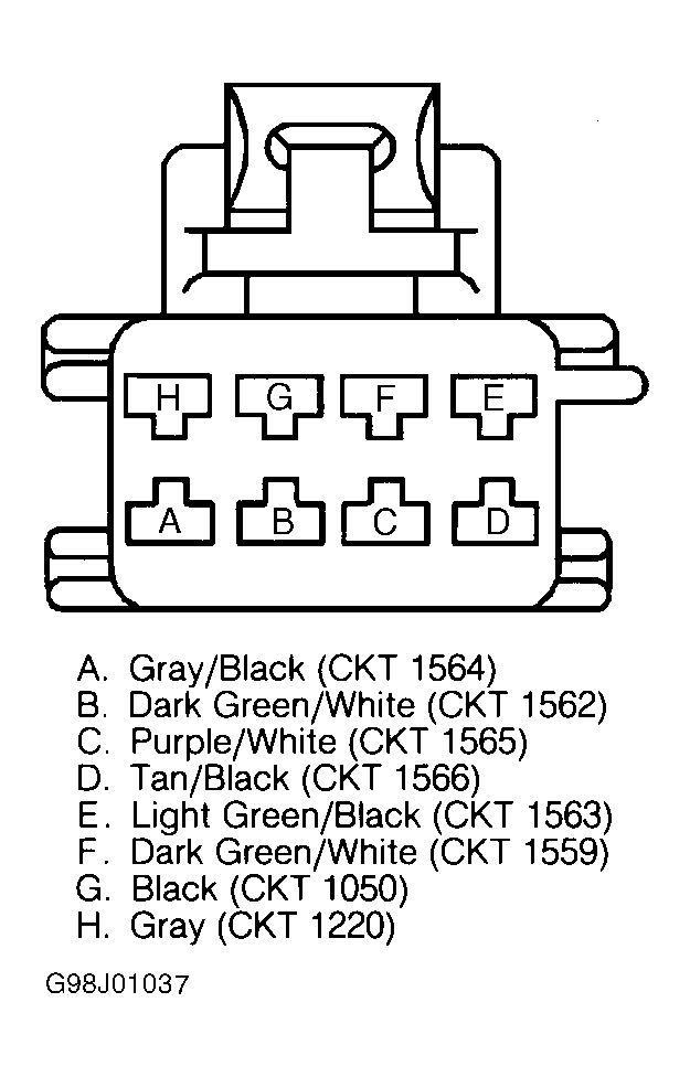 Courtesy of GENERAL MOTORS CORP.
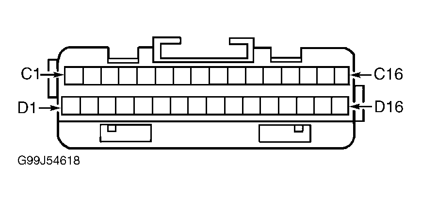 Courtesy of GENERAL MOTORS CORP.