P0123
Diagnostic Chart:
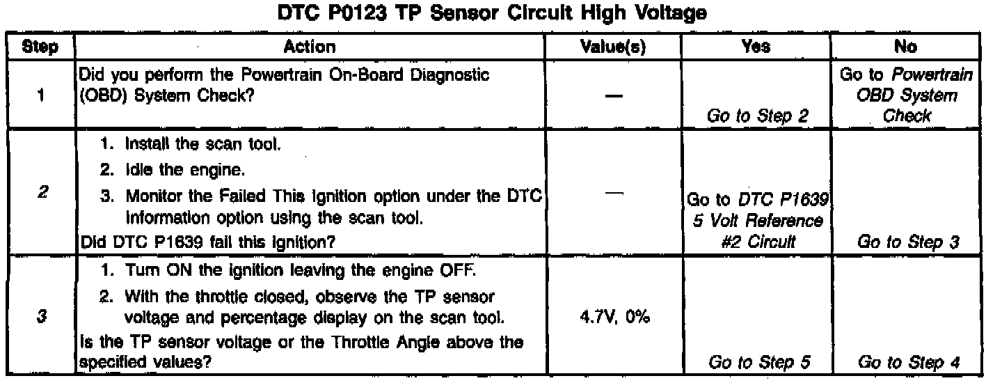
Diagnostic Chart:
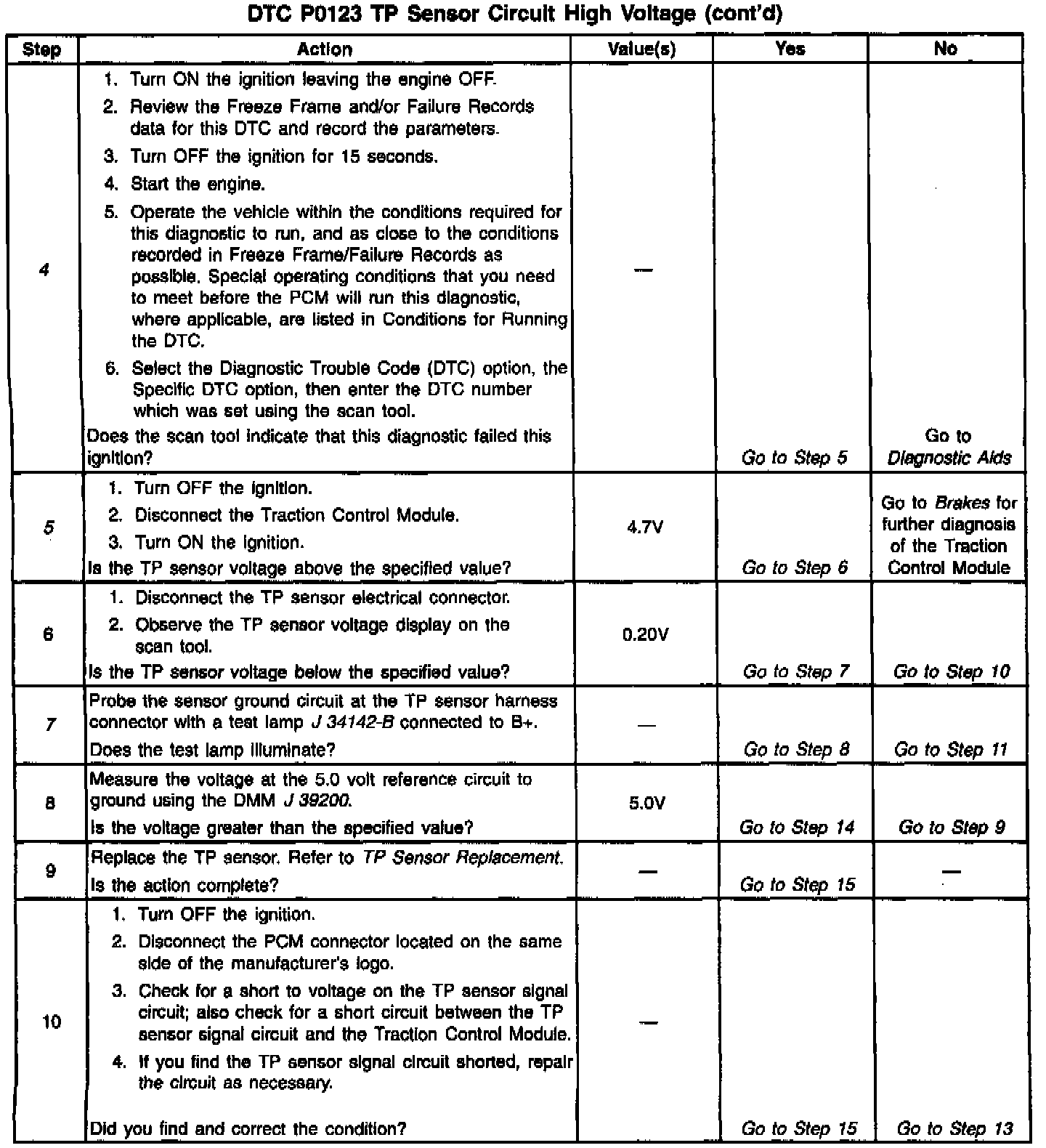
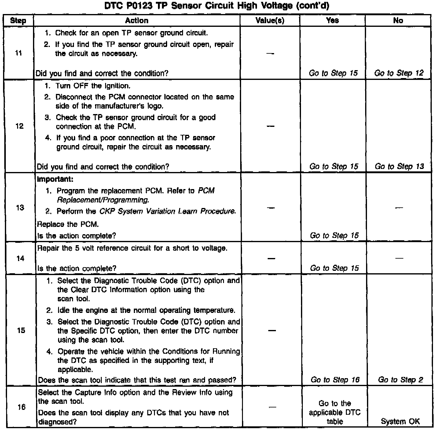
Diagnostic Chart:
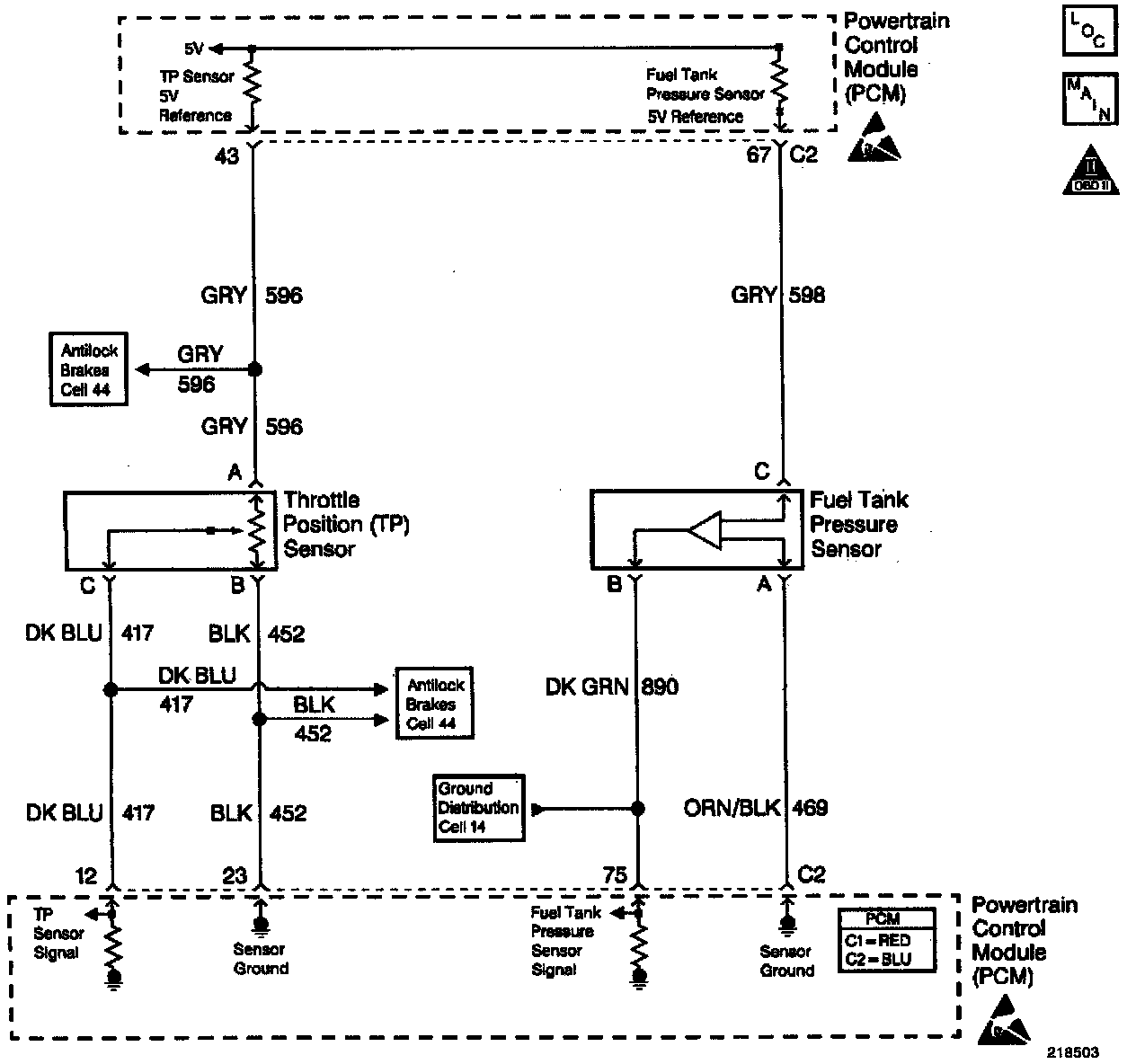
Wiring Diagram:
CIRCUIT DESCRIPTION
The Throttle Position (TP) sensor is a potentiometer. The TP sensor is mounted to the left side of the throttle body. The TP sensor provides a voltage signal that changes relative to throttle blade angle. This signal voltage is one of the most important inputs used by the PCM. The TP sensor has a 5.0 volt reference, a ground and a signal circuit. TP sensor Signal voltage should be about 0.6 volt at idle. The TP sensor voltage should increase to above 4.0 volts at wide open throttle (WOT). When the PCM senses a signal voltage higher than the normal operating range of the sensor, this DTC will set.
CONDITIONS FOR RUNNING The DTC
The ignition switch is in the ON position or the engine is operating.
CONDITIONS FOR SETTING THE DTC
- The TP sensor signal voltage is greater than 4.8 volts.
- Condition present for 10.0 seconds.
ACTION TAKEN WHEN THE DTC SETS
- The PCM illuminates the Malfunction Indicator Lamp (MIL) when the diagnostic runs and fails.
- The PCM records the operating conditions at the time the diagnostic fails. The PCM stores this information in the Freeze Frame and/or Failure Records.
- The PCM uses a default TP sensor value.
- The Transmission Torque Converter Clutch (TCC) will not apply.
- High transmission line pressure.
- Fixed transmission shift points, hard shifts and no fourth gear in hot mode.
CONDITIONS FOR CLEARING THE MIL/DTC
- The PCM turns the MIL OFF after three consecutive drive trips that the diagnostic runs and does not fail.
- A last test failed (current DTC) clears when the diagnostic runs and does not fail.
- A History DTC clears after forty consecutive warm-up cycles, if this or any other emission related diagnostic does not report any failures.
- The PCM battery voltage is interrupted.
- Use a scan tool in order to clear the MIL/DTC.
DIAGNOSTIC AIDS
- The following may cause an intermittent:
- Mis-routed harness.
- Rubbed through wire insulation.
- Broken wire inside the insulation.
- The PCM 5.0 volt reference circuits are internally connected within the PCM. If all the TP sensor circuits are OK, inspect the Fuel Tank Pressure Sensor for malfunctions.
- If it is determined that the DTC occurs intermittently, performing the DTC P1121 diagnostic table may isolate the cause of the fault.
- For an intermittent, refer to Symptoms. Testing and Inspection
TEST DESCRIPTION
The numbers below refer to the step numbers on the diagnostic table.
2. If DTC P1639 sets at the same time, this indicates that the 5.0 volt reference circuit is either shorted to a ground or shorted to a voltage, The 5.0 volt reference circuit is internally connected within the PCM.
3. This step checks if the fault is present.
4. Using Freeze Frame and/or Failure Records data may aid in locating an intermittent condition. If you cannot duplicated the DTC, the information included in the Freeze Frame and/or Failure Records data can help determine how many miles since the DTC set. The Fail Counter and Pass Counter can also help determine how many ignition cycles the diagnostic reported a pass and/or a fail. Operate vehicle within the same freeze frame conditions (RPM, load, vehicle speed, temperature etc.) that you observed. This will isolate when the DTC failed. For an intermittent condition, refer to Symptoms. Testing and Inspection
5. Vehicles equipped with traction control will have to disconnect the Traction Control Module. This will determine if the short is caused from the Traction Control Module. After repairs are made, reconnect the Traction Control Module and clear the DTCs that set when the Traction Control Module was disconnected.
7. This checks whether the ground circuit is available to the TP sensor. Check for poor electrical connections at the TP sensor. Refer to Repair Procedures in Electrical Diagnosis.